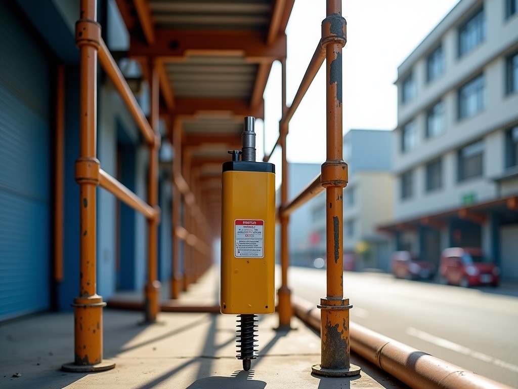
A lightweight screw jack is a mechanical lifting device that converts rotational motion into linear force through a threaded screw and nut assembly, designed to deliver controlled vertical or horizontal movement with reduced mass compared to conventional models. These units are engineered for applications where minimizing inertial load, simplifying installation, or meeting weight-sensitive structural constraints is critical, without sacrificing load capacity or positional accuracy. The core design principle focuses on optimizing material distribution and component geometry to achieve high strength-to-weight ratios, making them suitable for integration into mobile equipment, automated systems, and retrofit scenarios where existing support structures have limited load tolerance.
Unlike hydraulic or pneumatic alternatives, screw jacks operate without fluid compressibility or pressure loss, offering inherent self-locking capability under static load, which eliminates the need for continuous power or brake systems to maintain position. This characteristic enhances safety and energy efficiency in holding applications, while the mechanical simplicity reduces maintenance requirements and failure points associated with seals, valves, or compressors.
The lightweight nature of these screw jacks is achieved through strategic material selection and structural optimization, not by compromising on load-bearing components. Critical load paths—such as the screw shaft, worm gear, and housing mounting points—are typically constructed from high-strength alloy steels or hardened stainless grades to ensure durability under cyclic loading, while non-structural elements like housings, covers, and auxiliary brackets utilize aluminum alloys or reinforced engineering plastics to reduce mass.
Gear ratios are carefully selected to balance input torque requirements with desired lifting speed and efficiency. Higher gear ratios reduce the effort needed to lift heavy loads but decrease travel rate per input revolution, a trade-off quantified by the mechanical advantage formula: MA = (2π × lever arm) / (lead × gear ratio). Manufacturers often provide efficiency curves showing how worm gear friction impacts overall performance, particularly at low input speeds where self-locking thresholds become significant.
Axial load capacity, dynamic load rating, and buckling resistance are determined through finite element analysis and validated via static testing per ISO 14722 or ASME B30.1 standards. Deflection under load is minimized by optimizing the screw’s slenderness ratio and incorporating bearing support at both ends, preventing whipping or misalignment during operation—especially important in tall-column configurations where eccentric loads could induce bending stresses.
Material choice directly influences weight, corrosion resistance, and operational temperature range. Housing components are commonly produced from die-cast aluminum (e.g., A380 or ADC12) for its favorable density (~2.7 g/cm³) and castability, allowing complex internal geometries for gear mounting and lubrication channels. For environments requiring enhanced chemical resistance or food-grade compliance, 304 or 316 stainless steel housings may be specified, though this increases mass by approximately 3× compared to aluminum.
Screw shafts and worm gears are typically made from 42CrMo4 or equivalent chrome-moly steel, hardened to HRC 58–62 via quenching and tempering to resist wear and pitting under high contact stresses. In stainless steel variants, precipitation-hardened grades like 17-4PH are used to achieve comparable hardness while maintaining corrosion resistance. Surface treatments such as nitriding or chrome plating are applied selectively to threaded surfaces to reduce friction and extend service life in abrasive or humid conditions.
Lubrication is maintained through grease fittings or oil reservoirs, with synthetic lubricants recommended for wide temperature ranges (-20°C to +120°C) or food-safe applications. Sealing solutions vary from lip seals in dry environments to labyrinth or O-ring seals in washdown settings, with ingress protection ratings (IP54 to IP66) customizable based on exposure to dust, moisture, or cleaning agents.
| Parameter | Typical Range | Notes |
|---|---|---|
| Static Load Capacity | 0.5 – 20 kN | Dependent on screw diameter, material, and mounting configuration |
| Dynamic Load Rating | 0.3 – 15 kN | Based on L10 life at 20 rpm input speed |
| Screw Lead Options | 1 – 10 mm/rev | Affects travel speed and self-locking threshold |
| Gear Ratio (Worm) | 5:1 – 60:1 | Higher ratios increase mechanical advantage but reduce efficiency |
| Overall Efficiency | 20% – 50% | Varies with lead, ratio, lubrication, and load; lower at high ratios |
| Weight (Approximate) | 1.2 – 8.5 kg | For standard configurations; varies with housing material and stroke |
| Operating Temperature | -20°C to +120°C | Extended ranges available with special lubricants and seals |
| Ingress Protection (IP) | IP54 – IP66 | Customizable based on sealing options |
Note: Values represent typical industrial configurations. Actual performance depends on specific design, mounting conditions, and load dynamics. Custom stroke lengths, end fittings, and motor interfaces are available upon request.
In automated manufacturing systems, lightweight screw jacks are frequently integrated into conveyor height adjustment mechanisms, where rapid reconfiguration between product lines demands minimal downtime and low moving mass to reduce actuator sizing and energy consumption. Their self-locking property ensures precise positioning without power consumption during hold phases, making them ideal for battery-powered or energy-optimized automation cells.
Within aerospace and defense equipment, these jacks support maintenance access panels, radar array tilt mechanisms, or missile launcher elevation systems—applications where every kilogram saved improves fuel efficiency, payload capacity, or transportability. The absence of hydraulic fluid eliminates contamination risks in cleanroom or enclosed environments, while mechanical simplicity enhances reliability in remote or unattended operations.
For mobile industrial platforms such as automated guided vehicles (AGVs) or portable test rigs, lightweight screw jacks enable adjustable workholding or sensor positioning without overburdening the vehicle’s powertrain or suspension. Aluminum housings reduce unsprung mass, improving dynamic response and battery endurance, while corrosion-resistant coatings ensure longevity in outdoor or variable-climate deployments.
Engineers specifying lightweight screw jacks must evaluate not only static load but also dynamic factors such as acceleration/deceleration forces, lateral loading, and duty cycle. Applications involving frequent start-stop cycles or vibration exposure may require upgraded bearing systems, anti-backlash nuts, or damping interfaces to prevent premature wear or loss of positioning accuracy. Input interfaces—whether handwheel, motor flange, or shaft coupling—are standardized to accommodate common servo motors, stepper drives, or manual operators, with keyway or splined options available for torque transmission integrity.
Stroke length is a critical customization parameter, typically ranging from 50 mm to 600 mm in standard offerings, though extended travel is achievable through modular screw designs or stacked units. End fittings—including threaded rods, clevis joints, or spherical bearings—are selected based on load alignment requirements and tolerance for angular misalignment. For synchronized multi-point lifting, jacks can be linked via connecting shafts and bevel gearboxes to ensure uniform travel, with torque-limiting clutches or load-sharing controls preventing overloading of individual units.
Mounting flexibility is enhanced through configurable base plates, flange adapters, or weld-on brackets, allowing integration into existing frames without redesign. Thermal expansion compensation may be necessary in high-temperature environments, where differential expansion between screw and housing could induce preload changes or binding; solutions include sliding mounts or compensating couplings. Lubrication access points and vent plugs are positioned for ease of maintenance, with optional remote lubrication systems for inaccessible installations.
Manufacturing consistency is verified through dimensional inspection of critical interfaces—screw lead accuracy, gear tooth profiles, and housing bore concentricity—using coordinate measuring machines (CMMs) and gear analyzers. Lead deviation is typically maintained within ±0.05 mm per 300 mm to ensure predictable travel and prevent cumulative positioning error. Surface finish on threaded areas is controlled to Ra 0.4–0.8 μm to balance lubricant retention and wear resistance.
Each unit undergoes functional testing under incremental load cycles to confirm torque efficiency, self-locking threshold, and backlash characteristics. Breakaway torque is measured to validate static holding capacity, while input torque vs. load curves are recorded to assess mechanical efficiency across the operating range. For stainless steel variants, passivation treatments are validated via salt spray testing (ASTM B117) or humidity cabinet exposure to confirm corrosion resistance claims.
Final inspection includes verification of markings, documentation completeness, and packaging integrity. Traceability is maintained through lot-controlled materials and serialized components, enabling root-cause analysis in the event of field performance concerns. While specific certifications (e.g., CE, ISO 9001) depend on the manufacturer’s scope, quality processes generally follow industrial standards for mechanical power transmission components, emphasizing repeatability and traceability over third-party endorsements unless contractually required.
For technical specifications, customization options, or to discuss integration requirements for your application, please contact our engineering team.
Request Technical Consultation




