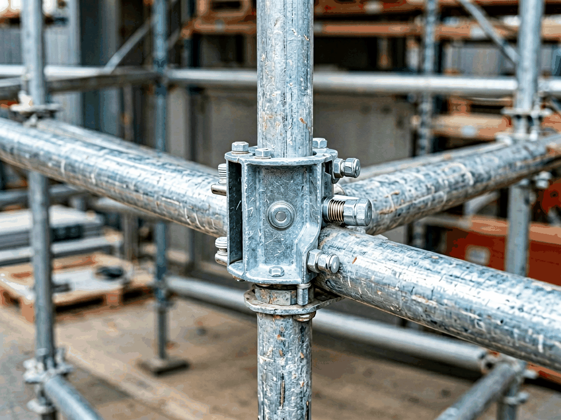
A beam clamp coupler is a mechanical fastening device used to connect scaffold tubes to structural steel beams without welding or drilling. It provides a secure, temporary attachment point for scaffolding systems in construction, maintenance, and industrial access applications. The coupler grips the flange of an I-beam, H-beam, or similar structural section using adjustable jaws and a threaded spindle, transferring load through friction and mechanical interlock. This method preserves the integrity of the host structure while enabling rapid erection and dismantling of temporary work platforms.
Beam clamp couplers consist of a malleable iron or forged steel body, hardened steel jaws, and a Acme-threaded spindle with a ergonomic handle. The jaws are shaped to match common beam flange profiles (typically 100–300 mm width) and include serrated contact surfaces to resist slip under load. The spindle applies clamping force perpendicular to the beam flange, generating sufficient frictional resistance to support design loads without damaging the beam coating or substrate. Most models include a safety pin or secondary locking mechanism to prevent accidental loosening due to vibration.
The safe working load (SWL) of a beam clamp coupler depends on bolt grade, jaw contact area, spindle thread integrity, and beam flange thickness. Typical SWL ratings range from 2.5 kN to 5.0 kN per coupler when used in accordance with manufacturer guidelines and relevant standards such as EN 74 or BS 1139. Load is applied axially along the scaffold tube, and the coupler must be installed with the spindle perpendicular to the beam flange to avoid eccentric loading. Engineers should verify flange thickness compatibility—most clamps accommodate flanges from 8 mm to 25 mm thick—and ensure the beam material has sufficient yield strength to resist local deformation under clamp load.
Bodies are commonly made from Grade 300 malleable iron for cost-effective durability or forged S355JR steel for higher impact resistance and tensile strength. Jaws are typically case-hardened to 55–60 HRC to resist wear from repeated clamping cycles. Spindles are manufactured from 8.8 grade alloy steel with rolled threads for improved fatigue life. Surface treatments include hot-dip galvanizing (minimum 55 µm zinc coating) for corrosion resistance in outdoor environments or zinc-plated with clear passivation for indoor use. Some models offer stainless steel (A2 or A4) construction for chemical or marine environments where galvanic corrosion is a concern.
Beam clamp couplers are designed to accept standard scaffold tubes with outer diameters of 48.3 mm (1.5 inch) or 42.4 mm, depending on regional standards. The coupler’s receiving socket includes a set screw or wedge mechanism to prevent tube rotation or axial movement under load. Compatibility must be verified—using a coupler rated for 48.3 mm tubes with 42.4 mm tubing reduces clamping efficiency and may compromise safety. Some adjustable models accommodate both sizes via interchangeable inserts, but fixed-socket designs require exact tube diameter matching for optimal performance.
Installation begins by placing the coupler over the beam flange and tightening the spindle by hand until the jaws make firm contact. The handle is then turned to apply additional torque—typically 80–120 Nm for malleable iron bodies—until the spindle reaches its mechanical stop or the safety pin can be inserted. Over-torquing can deform the jaw or strip threads, while under-torquing risks slip. A torque wrench is recommended for critical applications. After installation, verify that the scaffold tube sits flush in the socket and that there is no gap between the jaw and beam flange. Periodic retightening is advised after initial load cycling due to settling.
Beam clamp couplers are frequently used in petrochemical plants, power stations, shipyards, and large-scale renovation projects where welding is prohibited due to fire risk or coating preservation requirements. They enable rapid access scaffolding on overhead cranes, girder bridges, and roof trusses without penetrating protective coatings. In maintenance turnarounds, they allow crews to erect and dismantle scaffolding multiple times without damaging structural steel. Their reusability reduces lifecycle cost compared to welded brackets or penetrative fasteners, particularly in facilities with recurring access needs.
| Attachment Method | Installation Time | Impact on Structure | Reusability | Typical Use Case |
|---|---|---|---|---|
| Beam Clamp Coupler | 2–5 minutes per unit | No drilling/welding; surface-preserving | High (50+ cycles) | Temporary access on coated beams |
| Welded Bracket | 20–40 minutes per unit | Permanent; requires recoating | Low (single-use) | Permanent anchorage points |
| Drill-and-Bolt Anchor | 10–15 minutes per unit | Penetrates coating; risks corrosion | Medium (bolt reuse possible) | Where clamping geometry is unsuitable |
| Friction-Based Beam Clamp (no spindle) | 1–3 minutes per unit | No surface damage | Medium (jaw wear over time) | Low-vibration, light-duty applications |
Beam clamp couplers offer the best balance of speed, reversibility, and structural preservation for temporary scaffolding on structural steel. Unlike welded or bolted methods, they require no surface preparation or post-installation touch-up. Compared to simpler friction clamps, the threaded spindle provides consistent, adjustable clamping force suitable for higher loads and dynamic environments. The choice depends on load requirements, frequency of use, and beam accessibility—couplers excel when repeated installation cycles are anticipated.
Manufacturing follows ISO 9001 principles with dimensional inspection of jaws, spindle pitch diameter, and socket concentricity. Each batch undergoes proof load testing at 2x SWL to verify permanent deformation limits. Jaw hardness is spot-checked via Rockwell testing, and galvanizing thickness is measured using magnetic induction probes. Traceability is maintained via batch numbers stamped on the body, linking raw material certificates to final inspection reports. Couplers intended for EN 74 compliance are additionally tested for slip resistance under lateral load and cyclic fatigue.
Standard configurations cover common beam flange widths (100–300 mm) and thicknesses (8–25 mm). For non-standard beams—such as tapered flange sections, asymmetrical girders, or oversized columns—custom jaw profiles can be machined to match specific geometries. Spindle length and handle design can be adjusted for confined spaces or ergonomic improvement. Alternative thread types (e.g., trapezoidal or ACME) are available upon request for compatibility with existing inventory. Surface treatments can be upgraded to duplex systems (galvanized + epoxy) for aggressive environments, or supplied in self-color for indoor dry use where coating is unnecessary.
Units are packed in cardboard cartons with internal dividers to prevent jaw damage during transit. Typical carton quantities range from 20 to 50 pieces depending on size and weight. Each carton includes a installation manual and safety datasheet. For export shipments, cartons are stacked on pallets and secured with stretch wrap; corner protectors and edge boards are used to withstand forklift handling. Marine-grade packaging includes moisture-barrier liners and desiccant packs for long-sea transit. Markings include part number, SWL, material grade, and applicable standards for easy identification at point of use.
Before each use, inspect jaws for cracks, wear, or deformation—particularly at the serrated contact surfaces. Check the spindle for straightness, thread damage, or excessive play. Verify that the safety pin moves freely and is present. Clean threads and lubricate lightly with anti-seize compound to prevent galling. Store in a dry environment to avoid corrosion, especially if galvanizing is compromised. Any unit showing permanent deformation, thread stripping, or jaw wear beyond 20% of original profile should be removed from service and replaced.





