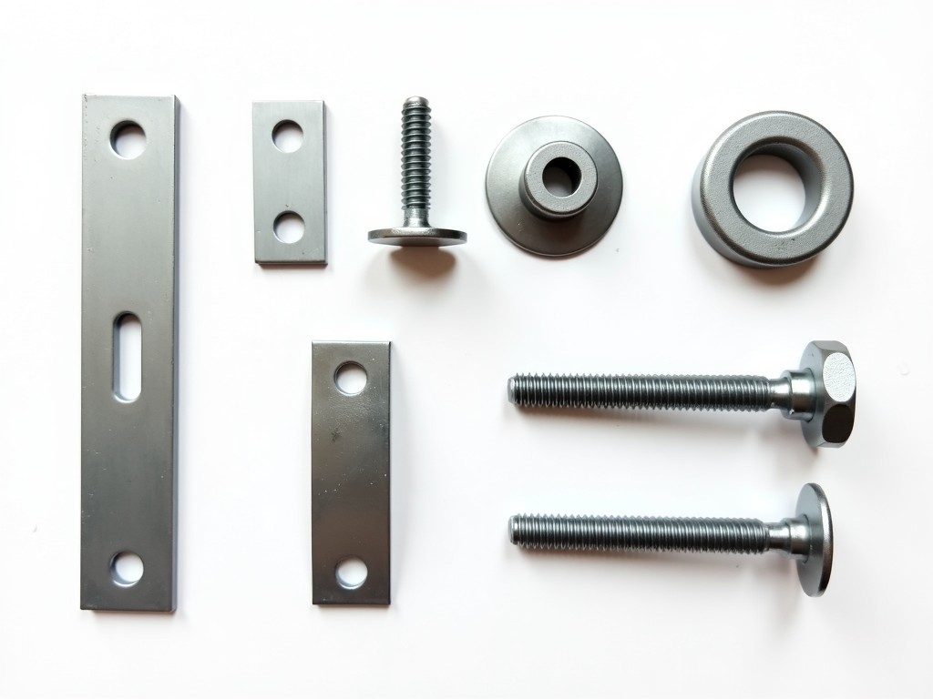
Scaffolding systems are temporary structures used to support workers and materials during construction, maintenance, and repair activities. Understanding the function and interaction of their core components is essential for safe assembly, load management, and compliance with occupational safety standards. Each part plays a specific role in transferring loads to the ground while maintaining stability under dynamic conditions.
The vertical load-bearing members, known as standards or uprights, transfer the combined weight of the platform, workers, and materials directly to the foundation or base plates. These are typically manufactured from steel tubes with an outer diameter of 48.3 mm and a wall thickness ranging from 3.2 mm to 4.0 mm, depending on the duty classification. Standards are connected horizontally using ledgers, which run parallel to the building face, and transoms, which span perpendicular to it, forming the primary grid that supports the working platform.
Ledgers and transoms are attached to standards via coupling devices such as right-angle couplers, swivel couplers, or putlog couplers, depending on the joint configuration. These couplers must withstand shear and tensile forces generated during use, with typical slip resistance values exceeding 15 kN when properly tightened to the recommended torque of 50–65 Nm. The spacing between standards usually ranges from 1.5 m to 2.5 m horizontally, while lift heights (vertical spacing between ledger levels) are commonly set at 2.0 m to balance accessibility and material efficiency.
The working platform consists of decking materials such as steel planks, aluminum frames with plywood or composite inserts, or laminated wood boards, placed transversely across transoms to create a continuous walking surface. Decking must deflect no more than L/200 under a uniformly distributed load of 2.0 kN/m² (light duty) to 3.0 kN/m² (medium duty), with individual planks typically overlapping adjacent supports by at least 150 mm to prevent uplift or tilting. Toe boards, usually 150 mm high, are installed along the platform edges to prevent tools or materials from falling.
Access to different levels is provided through ladder frames, stair towers, or integrated ladder sections within the scaffold bay. Ladder frames must align with the scaffold’s vertical modules and include rest platforms every 9 meters of vertical climb, as required by most international safety guidelines. Stair treads are designed with a rise of 170–200 mm and a going of 250–300 mm to ensure safe ascent and descent while carrying equipment, with handrails installed on both sides at a height of 900 mm to 1.1 m above the tread nosing.
Lateral stability is achieved through diagonal bracing, which can be installed as facade bracing along the building face or planar bracing within the scaffold bay. Facade braces are typically connected from the base of the standard to a point two lifts up and adjacent horizontally, forming a triangular configuration that resists racking forces caused by wind, eccentric loading, or accidental impact. Planar bracing, placed inside the bay, prevents longitudinal sway and is especially critical in freestanding or cantilevered scaffolds.
Base plates and adjustable screw jacks distribute the load from standards onto the ground or substructure, reducing ground pressure and compensating for uneven surfaces. Base plates are typically 150 mm × 150 mm steel squares with a central spigot to receive the standard, while screw jacks provide up to 300 mm of vertical adjustment. The allowable bearing capacity of the soil must be verified prior to erection, with typical ground pressures ranging from 120 kPa to 250 kPa depending on scaffold height and duty class.
| Component | Typical Material | Key Function | Dimensional Range |
|---|---|---|---|
| Standard (Upright) | Steel (S235JR or equivalent) | Vertical load transfer | 48.3 mm OD × 3.2–4.0 mm wall |
| Ledger | Steel tube | Horizontal longitudinal support | 48.3 mm OD × 2.6–3.2 mm wall |
| Transom | Steel tube | Platform support (transverse) | 48.3 mm OD × 2.6–3.2 mm wall |
| Coupler (Right-angle) | Forged steel | 90° tube connection | 50–65 Nm torque rating |
| Base Plate | Steel (stamped or forged) | Load distribution to ground | 150 mm × 150 mm × 6 mm thick |
| Toe Board | Steel or wood | Fall protection (tools/materials) | ≥150 mm height |
Guardrails, consisting of a top rail, mid-rail, and toe board, are required on all open sides of the platform where the height exceeds 2 meters to prevent personnel falls. The top rail must withstand a horizontal force of 0.6 kN applied at any point along its length without permanent deformation, while the mid-rail is positioned halfway between the platform and top rail to provide intermediate protection. These components are typically fastened using swivel couplers or proprietary clamping systems that allow adjustment to match the scaffold’s width and height.
In environments where scaffolding is subject to corrosive conditions—such as coastal areas, chemical plants, or high-humidity facilities—components may be specified with hot-dip galvanizing (minimum 55 μm zinc coating) or alternative protective coatings to extend service life. Regular inspection should focus on coupler tightness, plate deformation, corrosion at joints, and plank integrity, with damaged parts removed from service immediately regardless of visible wear.
Proper selection and assembly of these basic components ensure that scaffolding systems perform safely under expected loads while adapting to site-specific constraints. Engineers and supervisors should reference local regulations—such as OSHA 1926 Subpart L in the United States or EN 12810/EN 12811 in Europe—when designing or approving scaffold configurations, as these documents define minimum requirements for materials, connections, and inspection procedures.





