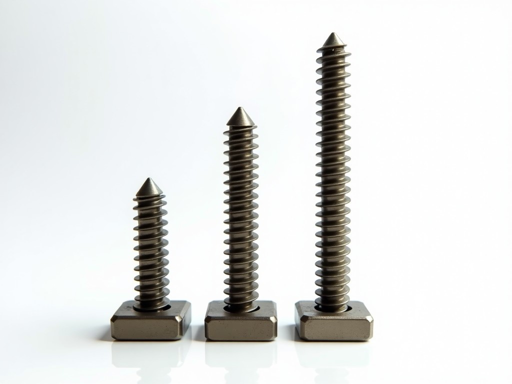
An adjustable square thread screw jack is a mechanical lifting device that converts rotary motion into linear motion using a square-threaded screw and a mating nut. Unlike ball screws or tapered threads, square threads offer high efficiency in power transmission with minimal friction loss under static or slow-moving loads, making them suitable for precision positioning and load-holding applications where back-driving must be prevented.
The adjustability feature refers to the ability to modify the effective stroke length or preload through external mechanisms such as threaded collars, lock nuts, or adjustable end stops, without disassembling the jack. This allows users to fine-tune travel limits or compensate for wear over time, extending service life and maintaining positional accuracy in cyclic operations.
Square thread geometry provides a 30–40% higher theoretical efficiency compared to Acme threads under equivalent load and lubrication conditions due to reduced sliding friction and absence of thread angle-induced radial forces. This results in lower input torque requirements for the same output force, reducing motor sizing and energy consumption in powered systems.
The screw and nut are typically manufactured from hardened alloy steel (e.g., 4140 or 4340) with surface hardness of 58–62 HRC after induction hardening or nitriding, ensuring wear resistance under sustained loads. Lubrication grooves or oil holes are often incorporated into the nut design to maintain a consistent film and prevent galling during extended operation.
Adjustment is commonly achieved via a lockable threaded collar positioned along the screw shaft or at the nut housing. Rotating the collar changes the effective engagement point, allowing stroke adjustment in increments as fine as 0.1 mm depending on thread pitch. A set screw or pin mechanism secures the collar against vibration-induced loosening.
| Parameter | Typical Range | Notes |
|---|---|---|
| Static Load Capacity | 5 kN – 500 kN | Dependent on screw diameter, material, and thread engagement length |
| Dynamic Load Capacity | 2 kN – 250 kN | Based on 10⁶ revolutions at 10% of static rating; lubrication and alignment critical |
| Thread Pitch Options | 2 mm – 12 mm | Finer pitch increases resolution; coarser pitch increases speed and load capacity |
| Max Input Torque | Up to 250 N·m | Limited by screw yield strength and thread shear area; safety factor ≥3 applied |
| Adjustment Range | ±5 mm to ±50 mm | Via external collar; maintains original thread integrity |
Load ratings are derived from ISO 3408 and ANSI B5.48 standards for power screws, applying conservative safety factors for static and fatigue conditions. Actual capacity depends on alignment, lubrication, temperature, and duty cycle. Side loads must be minimized — radial forces exceeding 5% of axial load can significantly reduce nut life due to edge loading.
Material selection is driven by environmental exposure, load cycle frequency, and maintenance accessibility. Stainless steel screws are preferred in food processing or outdoor installations where corrosion is a concern. Bronze nuts offer embeddability for minor misalignment but have lower wear resistance than steel; polymer nuts eliminate lubrication needs but are limited to lower loads and temperatures (<80°C).
In metal forming presses, adjustable square thread screw jacks are used to set die height precisely between cycles. The ability to micro-adjust stroke length compensates for tool wear and thermal expansion, ensuring consistent part thickness without stopping the line for manual shimming. This reduces setup time by up to 40% in high-mix stamping operations.
In automated assembly systems, they serve as vertical actuators for elevating work platforms or indexing tables. The self-locking nature of square threads prevents back-driving when power is removed, eliminating the need for brakes and simplifying control systems. Adjustment allows synchronization of multiple jacks in a gantry configuration to maintain platform levelness within 0.1 mm tolerance.
In industrial doors and access covers, they provide manual or motorized height adjustment for maintenance access. The lockable adjustment feature ensures the platform remains securely positioned during service, even under vibration or incidental impact, meeting OSHA 1910.23 requirements for elevated work surfaces.
Standard configurations include top plate, clevis end, or threaded rod end fittings. Custom ends can be machined to match existing linkages or mounting interfaces. Motor adaptation options include NEMA or IEC flange mounts for servo or stepper motors, with optional rotary encoders or limit switches integrated into the adjustment mechanism for closed-loop control.
For OEM integration, the jack can be supplied as a sub-assembly with pre-aligned housing and screw, reducing installation error. Adjustment collars can be fitted with dial indicators or digital readouts for direct stroke measurement. Protective bellows or scrapers are available to shield the screw from chips, coolant, or dust in machining environments.
All customizations are subject to engineering review to ensure thread engagement, buckling resistance, and critical speed limits are not exceeded. Customers must provide axial load, stroke length, input speed, duty cycle, and mounting constraints for proper sizing.
Each screw jack undergoes dimensional verification of thread pitch diameter, lead accuracy, and concentricity using coordinate measuring machines (CMM) or thread micrometers. Nut torque-to-turn tests are performed to confirm efficiency and breakaway torque within specified limits. Adjustment mechanism repeatability is validated over 50 cycles to ensure consistent positioning.
Load testing is conducted at 125% of rated static capacity for 5 minutes to verify structural integrity. No permanent deformation or thread galling is accepted. Surface treatments are inspected for adhesion and coverage using salt spray or humidity testing when specified. Final assembly includes functional stroke verification and lock torque validation.
Documentation includes material certificates, inspection reports, and a declaration of conformity to applicable mechanical safety standards. Traceability is maintained via serial numbers on screw, nut, and housing. Units are packaged with corrosion inhibitor and desiccant for storage or export.
To receive an accurate quotation and technical proposal, provide the following: required load (static and dynamic), stroke length, input speed (RPM or linear velocity), duty cycle (cycles per hour), mounting orientation, environmental conditions (temperature, humidity, contaminants), and desired end fittings. If motor-driven, specify motor type, voltage, and control interface.
For replacement or retrofit applications, include existing screw diameter, thread pitch, nut dimensions, and housing interface details. Sketches or 3D models are helpful but not mandatory. Our engineering team will validate compatibility and recommend any necessary adaptations.
Samples or test units are available upon request for evaluation in your application environment. Lead time for standard configurations is typically 4–6 weeks; custom designs require 8–12 weeks after drawing approval. All inquiries are answered within one business day by a mechanical engineer familiar with power screw applications.





