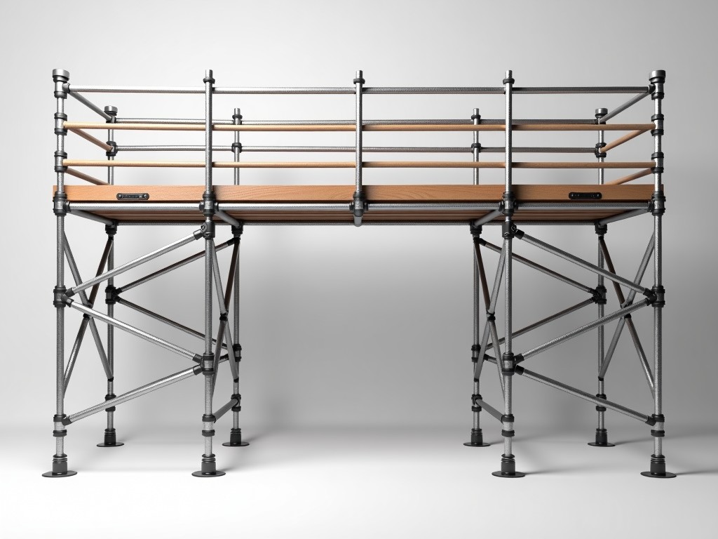
An adjustable jack base with U head is a critical component in modular scaffolding systems, designed to provide vertical load support while accommodating uneven ground conditions. The U head serves as the interface between the vertical standard and the horizontal ledger or bearer, transferring loads from the scaffold structure to the base. Unlike fixed bases, the adjustable jack allows precise height compensation through a threaded spindle mechanism, ensuring the scaffold remains level and plumb even on sloped or irregular substrates. This adjustability is essential for maintaining structural integrity and safety in temporary works, particularly in construction, renovation, and industrial maintenance applications where ground conditions vary across the site.
The core function of the jack base is to convert rotational input into linear displacement via a acme or trapezoidal thread spindle, typically manufactured from cold-drawn steel for high tensile strength and wear resistance. Rotation of the adjusting nut moves the U head vertically relative to the base plate, allowing fine-tuned elevation control—often within millimeter increments. The U head itself features a recessed channel (typically 50–60 mm wide) to securely hold scaffold tubes or standards, preventing lateral displacement under load. Load is transferred from the U head through the spindle to the base plate, which distributes the force over a larger area to prevent soil settlement or damage to finished surfaces such as flooring or pavement.
Material selection directly impacts durability, corrosion resistance, and load capacity. The spindle and adjusting nut are commonly made from 45# steel or equivalent carbon steel, hardened to HRC 20–25 for thread longevity under repeated adjustment cycles. The base plate is typically fabricated from Q235 hot-rolled steel plate, stamped or laser-cut to dimensions ranging from 150×150 mm to 200×200 mm, providing adequate bearing area for loads up to 25 kN per jack under typical scaffolding configurations. The U head is forged or machined from the same steel grade to ensure uniform mechanical properties and avoid weak points at stress concentrations. For environments with high moisture or chemical exposure, hot-dip galvanization (minimum 60 μm zinc coating) is applied to all components per ISO 1461, significantly extending service life compared to painted or untreated alternatives.
Load performance is governed by the mechanical advantage of the spindle thread and the compressive strength of the materials. A standard 24 mm diameter acme thread with 6 mm pitch provides approximately 5–7 mm of vertical adjustment per full rotation of the nut. Under axial load, the spindle resists buckling through its slenderness ratio and material yield strength; typical safe working loads range from 15 to 25 kN depending on extension length and end restraint. The base plate’s bearing pressure on soil must remain below the allowable ground pressure—often 100–150 kPa for compacted gravel or 50–100 kPa for sandy soils—to prevent settlement. Engineers calculate required base plate size based on tributary load and soil bearing capacity, ensuring the jack does not sink or tilt during use.
Adjustable jack bases with U heads are indispensable in scenarios where scaffolding must adapt to changing elevations or obstructions. In facade renovation, they enable precise alignment of working platforms with window sills, cornices, or balconies that follow irregular building contours. In industrial settings such as power plants or refineries, they compensate for uneven foundations around equipment foundations, trenches, or temporary roadways. During shoring and formwork for concrete pouring, they maintain exact elevation of soffit forms despite subsurface variations. Their adjustability also facilitates rapid dismantling and reconfiguration—critical in high-traffic urban construction where schedules are tight and site access is limited.
| Parameter | Typical Range / Value | Notes |
|---|---|---|
| Spindle Diameter | 20–28 mm | Acme or trapezoidal thread |
| Thread Pitch | 4–8 mm | Determines adjustment per rotation |
| Adjustment Range | 300–600 mm | Dependent on spindle length |
| Base Plate Size | 150×150 to 200×200 mm | Scales with load and soil conditions |
| Safe Working Load (SWL) | 15–25 kN | Per jack, depends on extension |
| Surface Treatment | Hot-dip galvanized (60+ μm) | ISO 1461 compliant |
| U Head Width | 50–60 mm | Accommodates 48.3 mm OD tube |
Quality control begins with material traceability—each batch of steel is accompanied by mill test certificates verifying chemical composition and mechanical properties. During manufacturing, spindle threads are rolled rather than cut to enhance fatigue resistance and surface hardness, followed by dimensional inspection using go/no-go gauges to ensure pitch diameter and flank angle conform to ISO 2901 or ASME B1.5 standards. Base plates are checked for flatness and perpendicularity using surface plates and dial indicators; any deviation beyond 0.5 mm per 100 mm is rejected. U heads undergo magnetic particle inspection to detect surface cracks, especially at the bend radius where stress concentrates. Final assembly includes functional testing: the nut is rotated through full travel under no load to verify smooth operation, then subjected to 110% of SWL for 3 minutes to confirm no permanent deformation or thread stripping.
Customization options exist to meet specific project demands without compromising safety or interchangeability. Spindle length can be adjusted to provide greater or lesser vertical range—common variants include 400 mm, 500 mm, and 600 mm overall extension—while maintaining the same thread diameter and pitch for compatibility with standard adjusting nuts. Base plate geometry may be modified: square plates are standard, but circular or rectangular variants are available for specialized load distribution or to fit confined spaces. For applications requiring electrical isolation (e.g., near live rails or welding zones), insulating sleeves or composite base pads can be supplied. Thread direction is typically right-hand, but left-hand spindles are offered upon request for tandem jack systems where synchronized adjustment is needed. All custom variants retain the same load ratings and material specifications as standard units unless otherwise validated through testing.
Procurement engineers should verify compatibility with their existing scaffolding system before purchase. The U head width must match the outer diameter of the vertical standard—most commonly 48.3 mm for steel tube scaffolding—though 60.3 mm variants exist for heavier-duty systems. The adjusting nut should feature a robust grip surface, such as knurling or welded handles, to allow effective torque application even with gloved hands or in low-light conditions. Spindle protection is critical: a threaded protector cap prevents dirt ingress and thread damage during storage and transport. When specifying, always confirm the galvanization thickness and adhesion quality—thin or uneven coatings compromise corrosion resistance, leading to premature failure in outdoor environments. Request mill certificates and test reports for load and material properties as part of the supplier’s quality documentation package.
In summary, the adjustable jack base U head is a precision-engineered load-transfer device that enables scaffolding systems to function safely and efficiently on non-uniform terrain. Its value lies not in complexity, but in the reliability of its core function: providing micro-adjustable, load-bearing elevation control through mechanically sound, corrosion-resistant components. By selecting based on measurable parameters—thread geometry, material grade, load capacity, and surface treatment—rather than superficial claims, buyers ensure long-term performance, reduced maintenance, and enhanced site safety. This component exemplifies how thoughtful design in temporary works hardware directly supports project timelines, cost control, and regulatory compliance.
For technical specifications, customization requests, or quotation details, please contact our engineering team.
Submit Inquiry




