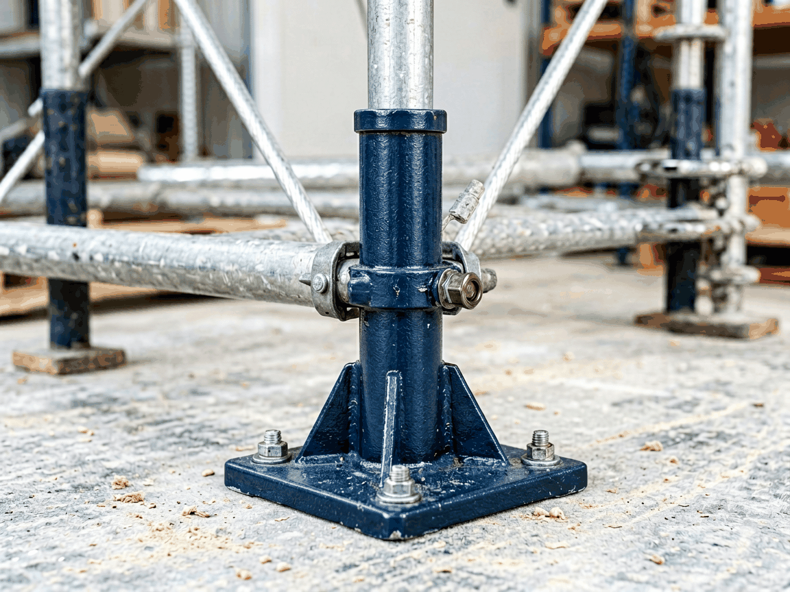
The adjustable base jack is a fundamental component in modular scaffolding systems, designed to provide vertical load transfer and precise height compensation on uneven substrates. It consists of a threaded spindle housed within a base plate, allowing controlled extension or retraction to level the scaffolding structure while maintaining axial load capacity.
The spindle operates via acme or trapezoidal threading, selected for its balance of strength, wear resistance, and ease of manual adjustment under load. Thread pitch typically ranges from 4 to 6 mm, enabling approximately 1 mm of vertical displacement per full rotation. This fine adjustment allows installers to compensate for substrate irregularities within ±25 mm without dismantling the scaffold.
The spindle is manufactured from cold-drawn steel bar, often C45 or equivalent, with a minimum tensile strength of 600 MPa. Surface hardening via induction or carburizing increases wear resistance at the thread interface, critical for repeated adjustment cycles under sustained load. The base plate distributes the reaction force over a larger area, reducing ground pressure to prevent settlement on soft soils.
Base plates are typically square or circular, with dimensions ranging from 120×120 mm to 150×150 mm for standard duty applications. Thickness varies between 8 and 12 mm, depending on expected load and substrate condition. The plate features a central collar or recess to prevent spindle lateral movement and ensure concentric load transfer.
On granular soils, the bearing area reduces unit pressure to acceptable levels (typically <100 kPa for compacted gravel). On cohesive soils, larger plates or supplementary sole boards may be required to prevent punching shear. The plate’s flatness and parallelism to the spindle axis are critical to avoid eccentric loading, which can induce bending stresses in the spindle.
Standard adjustment ranges fall between 300 mm and 600 mm, defined by the usable thread length before reaching mechanical stops or thread disengagement. Minimum extension ensures the spindle remains engaged within the nut housing to prevent thread stripping. Maximum extension is limited by buckling risk; effective length must comply with Euler buckling criteria based on end conditions and material modulus.
For example, a 500 mm adjustable spindle with a 25 mm diameter has a critical buckling load of approximately 18 kN when pinned at both ends—well below the typical yield load of 40 kN+, indicating that buckling, not material yield, often governs the upper load limit at full extension. Manufacturers specify safe working loads (SWL) at minimum, mid, and maximum extension to account for this nonlinear behavior.
Spindles and nuts are predominantly made from carbon steel due to cost-effectiveness and mechanical properties. Base plates may use the same material or be fabricated from ductile iron for improved impact resistance. In corrosive environments—such as coastal areas, chemical plants, or prolonged outdoor exposure—hot-dip galvanizing (minimum 55 µm zinc coating) is the standard protective measure.
Alternative coatings include electro-galvanizing for lighter exposure or powder coating for aesthetic and additional barrier protection. Stainless steel variants (e.g., AISI 304 or 316) are available upon request for hygienic or highly corrosive settings, though cost and galling potential in threaded interfaces limit widespread use.
Adjustable base jacks interface with scaffolding via a socket or receiver welded to the vertical standard (upright). Socket dimensions must match the spindle’s outer diameter and include a positive stop to prevent over-insertion. Common socket sizes are 38 mm, 48 mm, and 60 mm OD, corresponding to light, medium, and heavy-duty scaffolding tubes.
The jack must maintain concentric alignment with the standard to prevent lateral loading on the spindle. Some designs incorporate a swivel baseplate or tilting nut to accommodate minor slope variations while preserving vertical load path integrity. Compatibility is verified through physical fit testing and load transfer analysis, not merely dimensional matching.
Dimensional inspection focuses on thread pitch diameter, lead accuracy, and base plate flatness. Go/no-go gauges verify functional thread engagement. Surface hardness is checked at the thread crest and root using portable Rockwell testers. Straightness of the spindle is assessed over its full length; deviations exceeding 0.5 mm/m may induce bending under load.
Load testing is performed on sampling basis, applying incremental axial loads to 1.5× SWL while measuring deflection and monitoring for thread deformation or nut slippage. Visual inspection checks for cracks, discontinuities in coating, and proper weld integrity between spindle and nut retainer. Traceability is maintained via batch numbers linking to material certificates and inspection records.
| Parameter | Typical Range | Notes |
|---|---|---|
| Spindle Diameter | 25 mm – 32 mm | Affects buckling resistance and torque required for adjustment |
| Adjustment Range | 300 mm – 600 mm | Defined by usable thread length; custom lengths available |
| Base Plate Size | 120×120 mm – 150×150 mm | Larger plates reduce ground pressure on soft substrates |
| Surface Coating | Hot-dip galvanizing (55 µm min) | Alternative: electro-galvanizing, powder coating, stainless steel |
| Thread Type | Acme or trapezoidal | Selected for load capacity and wear resistance under frequent adjustment |
Values presented are typical for standard configurations. Actual specifications are determined by project load requirements, substrate conditions, scaffolding height, and duration of use. Custom threading lengths, plate geometries, or material grades are feasible upon engineering review.
In high-rise facade scaffolding, base jacks absorb differential settlement between foundation elements, maintaining platform levelness critical for worker safety and finish quality. In suspended scaffolding systems, they provide the primary load path from the building anchor to the suspended platform, where even minor misalignment can induce cable swing or uneven loading.
For shoring and formwork applications, the jack’s ability to sustain static loads over extended periods—often weeks or months—makes creep resistance a relevant factor. Stress-relieved spindles and stabilized microstructures reduce long-term elongation under constant load. In seismic zones, ductile base plate materials and certified weld procedures help prevent brittle failure during cyclic loading.
Regular inspection during use is advised: checking for thread damage, nut rotation under load, coating degradation, or base plate deformation. Lubrication of the acme thread with dry-film lubricant reduces friction and wear, preserving adjustment ease and preventing galling, particularly in humid or particulate-laden environments.





