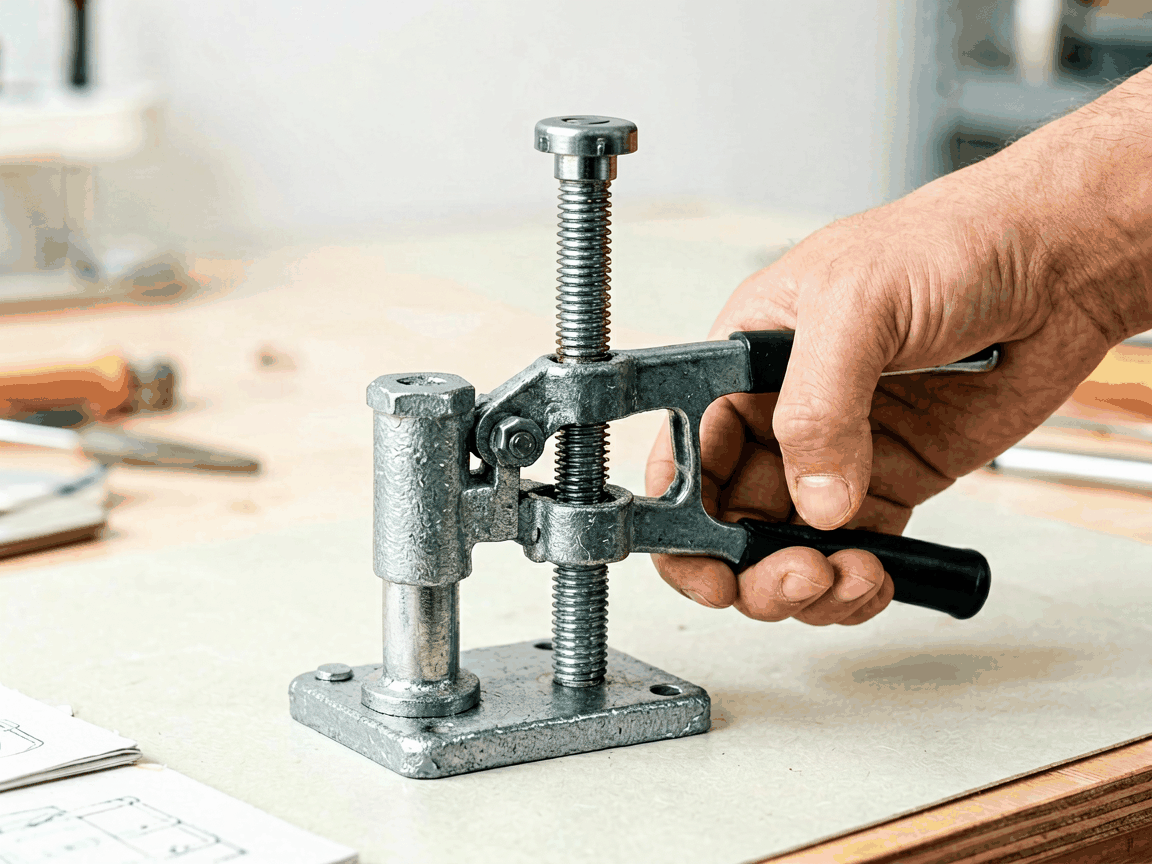
A four-way pressure clamp is a mechanical fastening device designed to apply uniform clamping force from four orthogonal directions simultaneously. Unlike single-axis clamps, this configuration distributes load evenly across a workpiece, minimizing deformation and improving alignment accuracy in assembly, welding, and machining operations. DIY variants allow engineers and technicians to adapt the clamp to specific project requirements using standard hardware and modular components.
The core principle relies on four independently adjustable screw or toggle mechanisms arranged at 90-degree intervals around a central mounting point. Each actuator applies force perpendicular to its axis, converging at the workpiece centroid. This vector summation results in a net clamping force with minimal moment, reducing the risk of part tilt or slip during processing. Proper force distribution depends on precise angular alignment and equal screw preload.
Modular DIY implementations typically use threaded rods, wing nuts, swivel pads, and base plates made from cold-rolled steel or aluminum alloy. The base plate provides a reference plane for mounting, while swivel pads compensate for surface irregularities. Adjustment range is determined by thread pitch and rod length; for example, an M8x1.25 thread with 50mm travel provides approximately 6.25mm of axial displacement per full turn.
Clamping force capacity is a primary design parameter, dictated by screw material grade, thread engagement length, and friction coefficients. For instance, an M8 socket head cap screw made of property class 8.8 steel can sustain approximately 18 kN of preload before yielding, assuming adequate lubrication and thread engagement of at least 1.5 times the nominal diameter. Exceeding this limit risks thread stripping or screw elongation.
Pad material selection affects both workpiece protection and force transmission. Hardened steel pads (HRC 55-60) are suitable for metallic workpieces where marring is acceptable, while polymer or brass inserts (e.g., UHMW-PE or C36000) prevent surface damage on softer materials like aluminum alloys or composites. Pad diameter should exceed the contact patch by at least 20% to avoid localized pressure peaks.
Base plate thickness influences system rigidity under load. A minimum thickness of 12mm is recommended for steel bases supporting clamps rated above 10 kN per axis to limit elastic deflection to under 0.1mm under full load. Finite element analysis shows that ribbed or gusseted designs can increase stiffness by 40% without significant weight gain, beneficial for portable DIY setups.
In precision welding fixtures, four-way clamps secure thin-gauge sheets during tack welding, preventing thermal distortion caused by uneven restraint. By applying balanced force, they reduce peak strain in the heat-affected zone by up to 30% compared to dual-axis clamping, as verified through strain gauge measurements on 1.2mm stainless steel assemblies.
During CNC machining of irregular castings, these clamps stabilize workpieces on modular tombstone fixtures where conventional vises cannot accommodate complex geometries. The four-point contact constrains all six degrees of freedom, enabling accurate 5-axis positioning without inducing stress concentrations that could lead to micro-cracking in brittle materials like gray iron.
In adhesive bonding operations, uniform pressure distribution ensures consistent glue line thickness, critical for structural joints in aerospace composites. DIY versions with adjustable pads allow compensation for curved surfaces, maintaining pressure within ±5% of target value across bonded areas exceeding 200mm², which directly impacts lap shear strength reliability.
Base plates are commonly fabricated from AISI 1018 cold-rolled steel for general use or 6061-T6 aluminum for reduced weight and corrosion resistance. Steel offers higher yield strength (~370 MPa) and stiffness (200 GPa), while aluminum provides one-third the density with adequate rigidity for loads under 5 kN per axis. Surface treatments like zinc plating or anodizing extend service life in humid environments.
Threaded components typically use alloy steel screws (e.g., 4140) hardened to HRC 38-42 for wear resistance, paired with bronze or nylon lock nuts to prevent vibrational loosening. Swivel pads may incorporate replaceable inserts—steel for hardened tooling beds, Delrin® for sensitive surfaces, or rubber-coated variants for vibration damping. Thread sizes range from M6 to M12, selected based on required force and adjustment precision.
Customization options include adjustable arm lengths via slotted bases, interchangeable pad kits for multi-material workflows, and integrated scale rings for repeatable preload setting. Some DIY builders incorporate dial indicators or load washers to monitor force in real time, enabling process validation without specialized equipment.
| Parameter | Typical Range | Notes |
|---|---|---|
| Clamp Force per Axis | 0.5 – 5 kN | Dependent on screw size and grade |
| Adjustment Range | 25 – 75 mm | Determined by thread length |
| Base Plate Thickness | 8 – 20 mm | Scales with load capacity |
| Pad Diameter | 12 – 25 mm | Larger for softer materials |
| Operating Temperature | -20°C to 120°C | Limited by pad material |
Begin by mounting the base plate to a stable reference surface using socket head cap screws or T-slot nuts, ensuring the plate is parallel to the workpiece plane within 0.1mm. Position the four actuators at equal angular intervals (90°) around the intended clamping point, verified with a protractor or machinist’s square. Insert swivel pads so they contact the workpiece surface perpendicularly.
Adjust each screw incrementally in a crisscross sequence (e.g., 1→3→2→4) to gradually build force while monitoring for workpiece movement. Use a torque wrench if repeatable preload is required—typical values range from 15 to 40 Nm for M8 screws, depending on friction conditions. Final verification includes checking for gaps under feeler gauges and confirming no visible deformation under load.
For dynamic applications, apply thread-locking compound (e.g., medium-strength anaerobic) to screw threads to prevent loosening from vibration. Periodic inspection should include checking pad wear, screw thread integrity, and base plate flatness. Replace pads when surface damage exceeds 0.5mm depth or when swivel motion becomes restricted.





