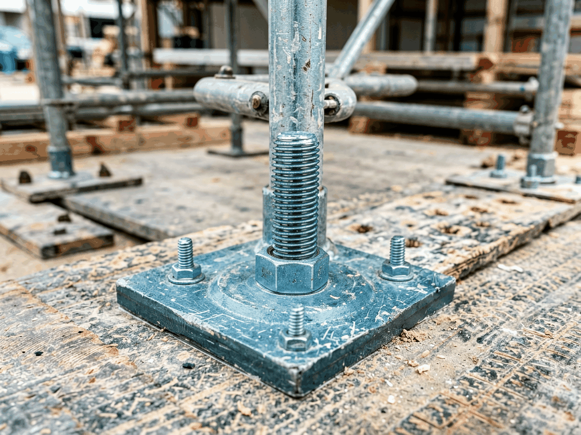
The scaffolding screw base jack plate is a foundational component designed to provide stable, adjustable support for temporary scaffolding systems. It transfers structural loads from vertical standards to the ground or substrate while compensating for uneven surfaces through mechanical adjustment. Unlike fixed base plates, this assembly incorporates a threaded spindle and nut mechanism allowing precise height modulation, which is essential for maintaining platform levelness across varying terrain. The design prioritizes load distribution efficiency, minimizing point pressure on soft or unstable substrates such as soil, gravel, or unfinished concrete. Proper selection and installation directly influence scaffolding rigidity, safety margins, and compliance with temporary works standards like EN 12811 or OSHA 1926 Subpart L.
The assembly consists of three primary elements: a load-distributing steel plate, a vertically threaded spindle (ACME or trapezoidal thread), and a manual adjustment nut with integrated handle or spanner interface. The base plate, typically ranging from 150x150mm to 200x200mm in plan dimension, spreads the scaffold’s reaction force over a sufficient area to prevent punching shear failure in the supporting material. Spindle diameter (commonly 25mm to 32mm) and thread pitch determine the mechanical advantage and adjustment resolution—finer threads allow smaller incremental changes but require more rotations for large adjustments. The nut often features a captive design to prevent disengagement during use, while a swivel socket at the spindle top accommodates slight angular misalignment of the scaffold standard without inducing bending stresses in the thread.
Load capacity is governed by the spindle’s buckling resistance and the plate’s bearing capacity, not the thread strength alone. For a 30mm diameter solid steel spindle with yield strength of 350MPa, Euler buckling analysis shows critical load exceeds 120kN when unsupported length is under 300mm—well above typical scaffold leg loads of 20-30kN per standard. However, real-world capacity is often limited by substrate bearing: a 150x150mm plate on compacted gravel (allowable bearing ~100kPa) supports approximately 22.5kN, making ground conditions the frequent design constraint. Manufacturers specify safe working loads (SWL) based on conservative assumptions for poor substrate conditions, with typical SWL ratings ranging from 15kN to 25kN per jack plate for general construction use.
Base plates and spindles are predominantly manufactured from structural carbon steel grades such as S235JR or A36, chosen for their balance of strength, ductility, and weldability. The spindle undergoes thread rolling (not cutting) to enhance fatigue resistance and surface hardness, while the plate is typically hot-rolled or forged to avoid internal defects. Surface treatment is critical for longevity in outdoor environments; hot-dip galvanizing to ISO 1461 standards (minimum 55μm zinc coating) is the industry norm, providing sacrificial protection that withstands years of exposure to moisture, alkaline concrete runoff, and atmospheric pollutants. Alternative coatings like zinc-rich primers or duplex systems are available upon request for aggressive industrial or marine environments, though galvanizing remains the most cost-effective solution for general use.
Material thickness directly affects plate rigidity and resistance to deformation under eccentric loading. A 6mm thick plate resists bending better than 4mm under off-center loads, reducing the risk of spindle tilting or plate curling. However, increased thickness adds weight—approximately 0.8kg per 100mm² per mm of thickness—impacting handling efficiency on large projects. Some designs incorporate reinforced corners or gussets to improve stiffness without uniformly increasing mass. For applications requiring non-magnetic properties (e.g., near MRI facilities), austenitic stainless steel grades like 304 or 316L are available, though their higher cost and lower yield strength (~200-250MPa) necessitate larger cross-sections to achieve equivalent load capacity.
The effective adjustment range is determined by the spindle length and the position of the stop mechanism preventing over-extension. Typical threaded lengths vary from 300mm to 600mm, providing usable ranges of 250mm to 500mm after accounting for minimum engagement depth in the nut (usually 1.5x spindle diameter for thread shear safety). Exceeding recommended extension risks thread stripping or nut ejection, particularly under dynamic loads. Some models feature a visible scale or stamped indicators on the spindle to aid consistent adjustment across multiple jacks—a practical feature for achieving uniform platform height in large bays. The handle or spanner socket on the nut is designed for torque application sufficient to overcome static friction; typical breakaway torque ranges from 25Nm to 40Nm for a 30mm spindle, achievable with a 200mm spanner applying ~150-200N rim force.
Self-locking capability depends on thread angle and friction coefficient. Standard ACME threads (29° included angle) with lubricated steel-on-steel contact have a friction angle sufficient to prevent back-driving under static loads, but vibration or impact can induce gradual creep. For critical applications where sustained position holding is mandatory, some designs incorporate a secondary lock nut or friction washer. Lubrication practices affect both adjustment ease and long-term thread wear; dry film lubricants or molybdenum disulfide coatings are preferred over grease in dusty environments to avoid abrasive paste formation. Regular inspection should verify thread integrity, nut rotation freedom, and absence of deformation in the plate or spindle.
These jack plates are indispensable in scaffolding systems where ground topography prevents uniform bearing—common in renovation projects, urban infill sites, or landscapes with existing foundations. By allowing independent adjustment at each standard, they enable the erection of level working platforms despite slope variations exceeding 100mm over a bay’s footprint. This capability reduces the need for extensive ground preparation or timber sole plates, accelerating setup time. In shoring and formwork applications, the same principle supports vertical elements under concrete load, where differential settlement must be accommodated to avoid inducing unintended stresses in the formwork facing or reinforcing steel.
Compatibility with scaffold standards is governed by the spigot or socket dimension at the spindle top. Most systems use a 48.3mm outer diameter (matching standard scaffold tube) with a captive socket or forged collar to prevent uplift. The connection must resist torsional moments from wind loading or lateral loads—typically addressed by a friction fit combined with a mechanical stop. When integrated into system scaffolding, the jack plate’s performance affects overall stability; excessive deflection at the base can amplify sway in tall structures. Engineers often specify base jack plates with known stiffness characteristics when conducting finite element analysis of scaffold assemblies, treating them as rotational springs with defined stiffness coefficients rather than rigid supports.
Dimensional consistency is critical for interchangeability and load predictability. Key controlled parameters include spindle straightness (typically <0.5mm/m runout), thread pitch accuracy (per ISO 724 or ASME B1.5), and plate flatness (<0.3mm deviation across diameter). Thread rolling is preferred over cutting for spindles due to superior surface finish, work hardening, and absence of stress concentrations. Plate dimensions are verified via calipers or coordinate measuring machines, while spindle length is measured between bearing surfaces to ensure consistent adjustment range. Magnetic particle inspection may be employed on high-stress areas like the thread root or plate-spindle weld (if applicable) to detect surface-breaking flaws.
Load testing validates design assumptions; sample jacks are subjected to incremental static loads to 1.5x SWL while measuring spindle deflection and nut rotation. Permanent set after unloading should remain below 0.1% of original length to confirm elastic behavior. Coating adhesion and thickness are verified via magnetic pull-off gauges and metallographic cross-sectioning per ISO 1460. Manufacturers may provide material test certificates (EN 10204 2.2) and coating reports upon request. Traceability is maintained through batch marking on the plate or spindle, linking each component to raw material certificates and process records—a requirement for auditable quality systems in regulated industries like petrochemical or pharmaceutical construction.
| Parameter | Typical Range | Notes |
|---|---|---|
| Base Plate Dimensions | 150x150mm to 200x200mm | Larger sizes reduce ground pressure but increase weight |
| Plate Thickness | 4mm to 8mm | 6mm common for balance of stiffness and weight |
| Spindle Diameter | 25mm to 32mm | Affects buckling resistance and thread strength |
| Thread Type | ACME or Trapezoidal (29° or 30°) | Self-locking under static load |
| Adjustment Range | 250mm to 500mm | Dependent on spindle length and stop position |
| Safe Working Load (SWL) | 15kN to 25kN | Often substrate-limited; consult geotech report |
| Coating | Hot-dip Galvanized (ISO 1461) | Min 55μm zinc; alternatives available |
| Material | S235JR / A36 Carbon Steel | Stainless steel options available |
Proper installation begins with substrate preparation—clearing loose debris, leveling obvious high points, and ensuring adequate bearing capacity. The jack plate should sit flat; shimming is discouraged as it introduces instability. Insert the scaffold standard into the spindle socket, ensuring full engagement before applying load. Adjust height by rotating the nut using the supplied handle or spanner; avoid impact tools that could damage threads. Once positioned, verify that all jacks in a bay are adjusted to carry proportional load—significant disparities indicate uneven settling or incorrect setup. Periodic retightening is recommended after initial load application due to substrate creep or joint settlement in the first 24 hours.
Never exceed the manufacturer’s specified SWL, and account for dynamic factors such as wind, equipment movement, or personnel load when calculating actual demands. In configurations with multiple standards per bay, load distribution should be verified through simple calculation or direct measurement if possible. Do not use extension tubes or improvised adapters between the jack plate and scaffold standard unless explicitly approved by the system manufacturer, as this alters the load path and may introduce bending moments. When dismantling, release load gradually before disengaging the standard to prevent sudden spindle ejection. Store components in a dry environment to prolong coating life, and inspect threads for debris or damage before reuse.
While standard configurations suit most scaffolding and formwork applications, certain projects require tailored solutions. Spindle length can be adjusted to match unique clearance constraints—such as low headroom in basement renovations—or to provide extended range for significant slope compensation. Base plate dimensions may be increased for use on extremely weak substrates like peat or loose fill, though this necessitates proportional increases in spindle diameter to maintain stiffness. For applications involving chemical exposure (e.g., fertilizer plants), custom coating systems such as fusion-bonded epoxy or thermoplastic wraps can be specified, though lead time and cost increase accordingly.
Thread direction is typically right-hand, but left-hand variants exist for specialized tensioning applications where reverse rotation would occur under load—though these are rare in scaffolding. Some manufacturers offer integrated base plates with pre-welded drainage channels or reinforced lifting lugs for handling efficiency. Custom markings, such as company logos or identification numbers, can be applied via laser etching or stamping without compromising coating integrity. When requesting non-standard configurations, provide detailed load cases, substrate data, and dimensional constraints to enable accurate engineering evaluation—avoiding assumptions ensures the final product meets safety and performance expectations.





