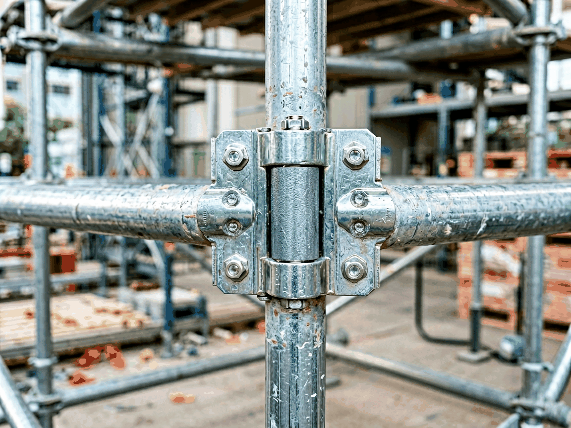
The scaffolding hinge coupling pin connector is a precision-engineered component designed to join scaffold tubes at variable angles while maintaining structural integrity under load. It enables rapid assembly and disassembly of temporary access structures in construction, maintenance, and industrial settings.
The connector consists of a forged steel hinge body with two tubular sleeves that accept standard 48.3mm OD scaffold tubes. A hardened steel pin passes through aligned holes in the hinge and tubes to lock the assembly. The hinge mechanism allows angular adjustment from 0° to 180°, enabling configurations such as bracing, corner joints, and inclined supports without custom fabrication.
Load transfer occurs primarily through shear resistance of the pin and bearing contact between the tube and sleeve. The design minimizes stress concentrations by distributing load across the full bearing surface of the hinge knuckle. Pin diameter is typically 16mm or 20mm, selected based on expected load conditions and tube wall thickness.
The hinge body is manufactured from normalized carbon steel (e.g., C45 or equivalent) to achieve a balance of tensile strength (>600 MPa) and toughness. The pin is made from hardened alloy steel (e.g., 42CrMo4) with a surface hardness of HRC 50-55 to resist wear and deformation. Sleeves are machined to precise tolerances (H7 for tube fit, h6 for pin hole) to ensure minimal play and consistent alignment.
Forging is preferred over casting for the hinge body to eliminate internal voids and improve grain flow directionality, enhancing fatigue resistance. All critical surfaces are machined post-forging to achieve dimensional accuracy. Zinc plating (minimum 8µm thickness) or hot-dip galvanizing is applied for corrosion protection in outdoor environments.
The connector’s safe working load (SWL) depends on pin shear strength, tube bearing capacity, and hinge joint stability. For a 20mm pin in C45 steel, theoretical shear capacity exceeds 40 kN, but practical SWL is limited by tube deformation and connection stability. Typical SWL ratings range from 15 to 25 kN per connector when used with 3.2mm wall thickness scaffold tubes, based on empirical testing and industry standards such as EN 12810-1.
Angular adjustment does not significantly reduce load capacity within the 0°–180° range, as load is transmitted axially through the tubes rather than resisted by the hinge angle. However, eccentric loading at extreme angles may induce bending moments in the tubes, requiring engineering assessment for critical applications.
| Parameter | Standard Duty (16mm Pin) | Heavy Duty (20mm Pin) |
|---|---|---|
| Pin Diameter | 16 mm | 20 mm |
| Hinge Body Material | C45 Steel | C45 Steel |
| Pin Material | 42CrMo4 (HRC 50-55) | 42CrMo4 (HRC 50-55) |
| Typical SWL (3.2mm Tube) | 15 kN | 25 kN |
| Weight per Unit | 0.85 kg | 1.2 kg |
| Surface Finish | Zinc Plated (8µm) | Hot-Dip Galvanized |
This connector is commonly used in facade scaffolding where building contours require angled supports, such as around balconies, cornices, or irregular elevations. It allows installers to maintain consistent tube spacing and load paths without cutting or bending tubes, preserving material reuse and reducing on-site labor.
In shoring and formwork systems, the hinge connector enables the construction of inclined raker shores to resist lateral loads from wet concrete. The ability to adjust the angle in situ accommodates variations in foundation slope or wall batter, improving system adaptability during multi-phase pours.
For suspended access platforms, the connector facilitates the creation of safety railings and toe boards at non-standard angles, ensuring compliance with fall protection regulations while conforming to complex geometries. Its quick-release pin allows for rapid reconfiguration during maintenance campaigns.
Each production batch undergoes dimensional verification of critical features: pin hole alignment tolerance (±0.15mm), tube sleeve concentricity (<0.2mm runout), and hinge pivot smoothness (max 0.5Nm breakaway torque). Mechanical properties are validated through spot hardness testing (pin: HRC 50±3; body: HRB 85±5) and tensile sampling of raw material.
Surface coating thickness is measured via magnetic induction (min 8µm for zinc, min 55µm for galvanizing). Visual inspection checks for forging laps, cracks, or burrs that could compromise stress distribution. Units are functionally tested by assembling with standard tubes and applying cyclic load to verify pin retention and hinge integrity.
Traceability is maintained through batch markings on the hinge body, linking to material certificates and test records. Packaging includes corrosion-inhibiting spacers and moisture-barrier wrapping for sea transport, with clear labeling of SWL, material grade, and applicable standards.
Non-standard configurations are available upon request, including alternative pin diameters (12mm, 25mm), extended sleeve lengths for oversized tubes, or stainless steel grades (e.g., 316L) for corrosive environments. Hinge range can be limited to specific angles (e.g., 90° fixed) for dedicated bracing applications where adjustability is not required.
To receive an accurate quotation, provide tube outer diameter, wall thickness, expected load direction and magnitude, required quantity, and delivery timeline. For projects requiring certification, specify whether EN 12810, ANSI/ASSE A10.8, or local scaffolding standards apply. Samples can be supplied for validation prior to bulk order.





