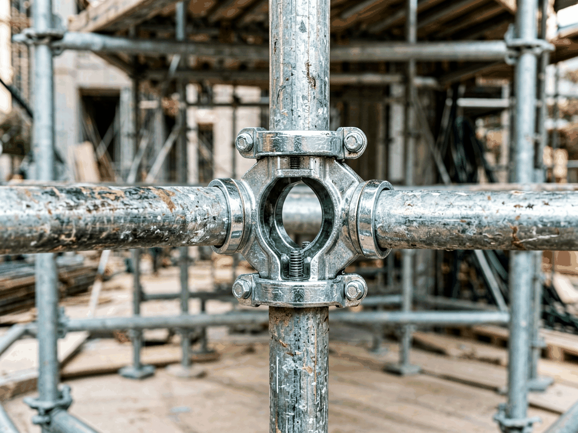
The double clamp fixed coupler is a fundamental component in tube-and-coupler scaffolding systems, designed to create a rigid 90-degree connection between two scaffold tubes. Unlike swivel couplers that allow angular adjustment, this variant locks tubes at a fixed perpendicular angle, providing critical structural stability in vertical and horizontal bracing applications. Its primary function is to resist lateral loads and maintain geometric integrity under dynamic site conditions, making it essential for load-bearing frameworks where precise angular alignment is non-negotiable.
Manufactured from drop-forged steel, the coupler consists of two opposing jaws, each equipped with a hardened steel bolt and nut assembly. When tightened, the jaws clamp securely onto the outer diameter of scaffold tubes, typically 48.3 mm in outer diameter for standard systems. The fixed geometry ensures that connected tubes maintain exact 90-degree orientation, preventing rotational slippage that could compromise structural calculations in facade support, shoring, or suspended scaffolding configurations.
Material selection directly impacts performance, durability, and compliance with international scaffolding standards such as EN 74, BS 1139, or ANSI/ASSE A10.8. The coupler body is typically forged from carbon steel grades like C45 or equivalent, chosen for its balance of tensile strength (≥ 500 MPa) and ductility, allowing plastic deformation before fracture under overload conditions—a key safety feature. Surface treatment varies by environmental exposure: hot-dip galvanization (minimum 55 µm zinc coating) is standard for outdoor use to resist corrosion, while electro-galvanized or painted finishes may suit temporary indoor projects with controlled humidity.
Critical dimensions include jaw throat depth (typically 25–30 mm to accommodate tube deformation under load), bolt diameter (commonly M16 or M18), and required torque values (usually 50–70 Nm for proper clamping force without thread stripping). The fixed angle is maintained within ±1° tolerance during manufacturing to ensure alignment accuracy when integrated into grid systems. These parameters are not arbitrary; they derive from finite element analysis of load paths and empirical testing under cyclic loading to prevent fatigue failure at stress concentrations near the bolt holes.
| Parameter | Typical Value | Standard Reference |
|---|---|---|
| Tube Compatibility (OD) | 48.3 mm | EN 74-1 |
| Material Grade | C45 / 1.0503 | EN 10083-2 |
| Surface Treatment | Hot-dip Galvanized | EN ISO 1461 |
| Bolt Size | M16 x 50 mm | ISO 898-1 |
| Recommended Torque | 60 Nm | EN 74-2 Annex B |
| Angle Tolerance | ±1° | Manufacturer QC |
The coupler’s load-bearing capacity is not defined in isolation but as part of a connected system. Under ultimate limit state conditions, a properly installed double clamp fixed coupler can resist characteristic loads exceeding 20 kN in shear perpendicular to the tube axis, depending on tube wall thickness (e.g., 3.2 mm vs. 4.0 mm) and bolt torque. This capacity arises from frictional resistance between the jaw and tube surface, augmented by mechanical interlock from the forging geometry. Slippage typically initiates when clamping force drops below thresholds required to overcome static friction, emphasizing the importance of correct torque application during assembly.
In long-span applications, such as birdcage scaffolds supporting formwork, the coupler’s resistance to rotational movement prevents parasitic moments that could induce premature buckling in standards. Engineers account for this by treating fixed connections as rigid nodes in structural models, which significantly influences deflection calculations and natural frequency estimates. Conversely, underestimating this rigidity can lead to unconservative designs, while over-reliance without accounting for potential bolt loosening introduces hidden failure modes—hence the need for periodic retorque inspections in dynamic environments.
This coupler excels in scenarios where geometric precision dictates safety and functionality. In facade scaffolding for high-rise buildings, it connects ledgers to standards at exact right angles, ensuring uniform load distribution across the facade and preventing racking under wind loads. Similarly, in shoring towers for concrete slab support, fixed couplers join diagonal braces to vertical members, creating triangulated systems that efficiently transfer compressive loads to the foundation without lateral sway.
Specialized uses include suspended scaffolding where outriggers require perpendicular attachment to main tubes, and stage rigging systems where lighting trusses must maintain precise angular alignment for load calculations. Unlike adjustable couplers, the fixed variant eliminates reliance on operator judgment for angle setting, reducing human error in repetitive grid assemblies. For temporary structures like event grandstands or access towers, its predictability simplifies engineering approvals, as connection behavior is well-documented in standards and less prone to variability from installation technique.
Consistent performance begins with controlled forging processes. The coupler jaws are typically hot-forged in closed dies to achieve precise grain flow that follows the contour of the clamping area, enhancing fatigue resistance. Post-forging, components undergo normalization to relieve internal stresses before machining of bolt holes and thread tapping. Dimensional inspection focuses on critical features: jaw parallelism, bolt hole perpendicularity to the clamping plane, and angularity of the fixed 90-degree feature—all verified using coordinate measuring machines (CMM) or specialized fixtures.
Mechanical testing includes proof load assessments where couplers are subjected to incremental forces until permanent deformation occurs, validating that design loads remain within the elastic range. Surface coating integrity is checked via adhesion tests (e.g., cross-hatch per ASTM D3359) and thickness measurements using magnetic or eddy-current probes. Traceability is maintained through batch markings linking raw material certificates to final inspection reports, a requirement for projects governed by stringent quality regimes such as nuclear infrastructure or petrochemical plant maintenance.
Understanding the functional differences between coupler types aids in correct specification. A swivel coupler allows 360-degree rotation, making it suitable for bracing at arbitrary angles but introducing potential play under reversing loads. A putlog coupler, designed to bear on a single tube (e.g., supporting a putlog transom), lacks the symmetrical clamping action of a double clamp and is unsuitable for tube-to-tube connections requiring mutual support. The double clamp fixed coupler uniquely combines symmetrical load sharing with angular rigidity, making it the preferred choice for primary grid connections where both tubes are load-bearing members.
Cost-wise, fixed couplers are generally less expensive than swivel variants due to simpler geometry and fewer moving parts. However, substituting a fixed coupler where angular flexibility is needed—such as in irregular façade adapters—can induce stress concentrations or require compensatory bending of tubes, negating any savings. Conversely, using a swivel coupler in a fixed-angle application risks gradual loosening under vibration, necessitating more frequent maintenance. Selection should therefore align with the structural role: fixed for primary grids, swivel for secondary bracing, and putlog for end-bearing scenarios.





