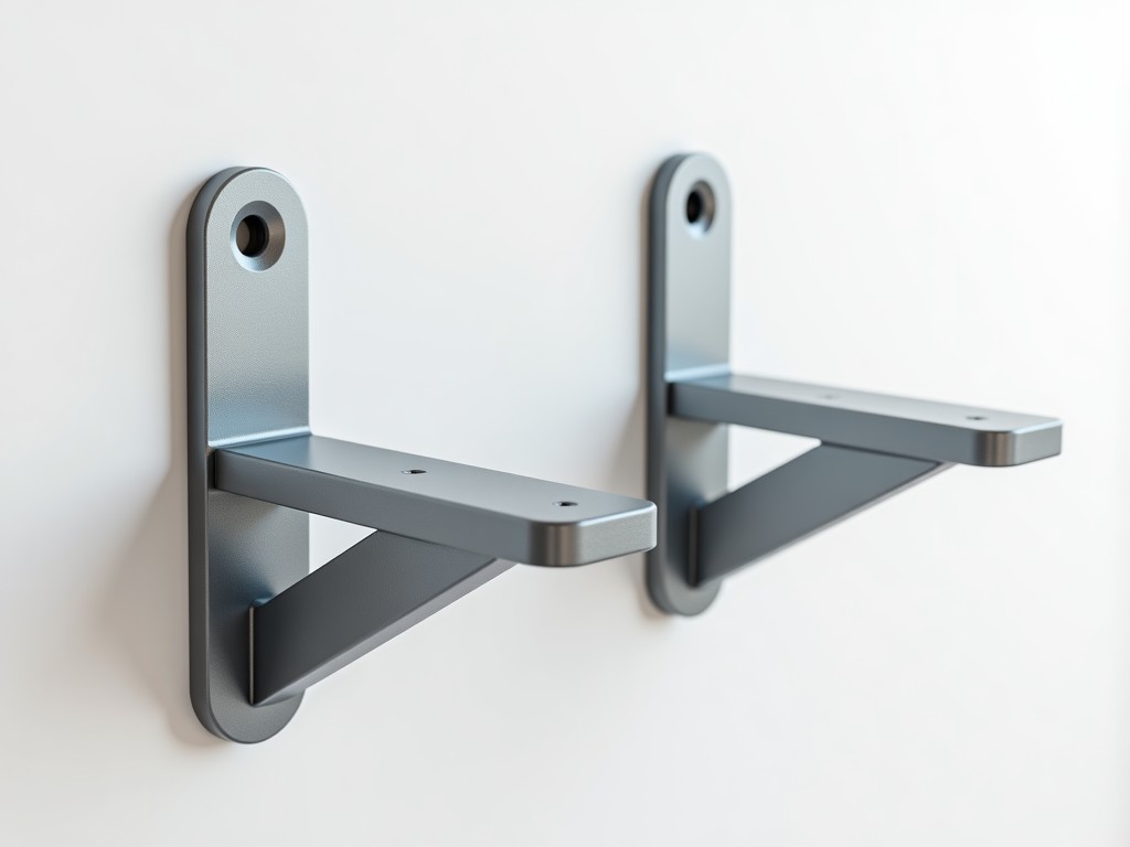
Cantilever brackets are critical load-transfer components in supported scaffolding systems, designed to extend working platforms beyond the building face where direct ground support is impractical or obstructed. These brackets cantilever from the wall structure, creating a stable horizontal ledger support at elevation without requiring ground-based standards or toe-boards in the blocked zone. Their design must account for eccentric loading, wall anchorage strength, and rotational stability under combined dead and live loads as defined in EN 12810/12811 and OSHA 1926 Subpart L.
The primary function of a wall-mounted cantilever bracket is to transfer platform loads—personnel, materials, and equipment—through a rigid arm into a secure wall anchorage system. Unlike putlog brackets that bear on the wall surface, cantilever brackets apply a moment load at the anchorage point, requiring the wall substrate to resist both withdrawal and shear forces. The bracket arm acts as a simple beam fixed at the wall interface, with deflection limited to L/150 under service load to prevent platform instability and guardrail misalignment.
Load testing follows EN 12811-2:2003 Annex B, applying a vertical test load of 1.5 kN at the platform support point while measuring deflection and rotation at the wall connection. Acceptable performance requires residual deformation under 2 mm after unloading and no signs of bolt slippage or plate deformation. Anchorage design must consider substrate characteristics—solid concrete, hollow block, or steel framing—each requiring specific fastening methods and edge distance minimums to prevent spalling or pull-through failure.
Bracket arms are typically fabricated from structural steel grades S275JR or S355JR, chosen for their yield strength (≥275 MPa or ≥355 MPa) and ductility under cyclic loading. The wall connection plate uses the same grade to ensure weld compatibility and consistent thermal expansion. For exterior applications in corrosive environments, hot-dip galvanization per EN ISO 1461 provides a minimum zinc coating of 55 µm, offering 15–25 years of maintenance-free service in C3 urban/industrial atmospheres.
Alternative materials include stainless steel (grade 1.4401/316) for chloride-exposed zones such as coastal structures or chemical plants, where pitting resistance equivalent number (PREN) >24 is required. Aluminum alloys (EN AW-6082 T6) are used in weight-sensitive applications like temporary facade access on lightweight structures, though their lower modulus of elasticity (≈70 GPa vs 200 GPa for steel) necessitates larger sections to limit deflection. Material test certificates (EN 10204 3.1) are available upon request for all primary structural components.
Cantilever brackets are available in fixed and adjustable configurations to accommodate varying wall offsets and course heights. Fixed brackets offer simplicity and higher stiffness, with standard arm lengths of 0.5 m, 0.75 m, and 1.0 m, selected based on the required platform extension and wall clearance. Adjustable variants use telescoping tubes with positive locking pins, allowing on-site length adjustment in 50 mm increments from 0.4 m to 1.2 m, reducing the need for multiple bracket inventories on complex façades.
Wall connection interfaces include flat base plates for direct bolting, angled brackets for soffit or soffit-and-wall applications, and channel brackets designed to slot into pre-installed steel channels or concrete inserts. Base plate hole patterns follow common flange standards (e.g., 100x100 mm with M16 holes at 75 mm centers) to accommodate anchor bolts, chemical anchors, or through-bolts with backing plates. All designs maintain a minimum 6 mm plate thickness at the anchorage zone to prevent local bending under prying forces.
Proper installation begins with verifying substrate integrity—concrete must achieve minimum compressive strength of 25 N/mm² at 28 days, and masonry units should be sound, unbroken, and properly bonded. Anchorage points are spaced to match the bracket’s base plate, typically at 600 mm vertical intervals to align with scaffolding lift heights. Hole drilling uses carbide-tipped bits matched to anchor diameter, with hole cleaning via blow pump and brush to remove dust critical for adhesive bond or mechanical interlock.
Anchor selection depends on substrate and load: chemical anchors (epoxy or polyester) are preferred for hollow or variable substrates, offering adjustable embedment and high tension capacity; mechanical expansion anchors suit solid concrete with consistent edge distances; through-bolts with steel backer plates are used where access permits. Torque application follows manufacturer specs—typically 80–120 Nm for M16 chemical anchors—to ensure proper preload without overstressing the substrate. A level is used to ensure the bracket arm is horizontal within ±2° before attaching ledgers or transoms.
Manufacturing adheres to EN 1090-2 for execution of steel structures, with welding procedures qualified per ISO 15614-1 and non-destructive testing (visual and dye penetrant) on 100% of full-penetration welds. Dimensional tolerances follow ISO 2768-m: arm length ±2 mm, hole position ±0.5 mm, and flatness of connection plates <0.3 mm over 100 mm. Each bracket is marked with batch number, material grade, and CE conformity symbol where applicable, enabling full traceability.
Load testing is conducted on a sampling basis per EN 12811-2, with destructive testing performed on first article and periodic batches. Surface preparation for galvanization meets Sa 2.5 standard, with coating thickness verified via magnetic induction gauge. Documentation includes material certificates, weld procedure specifications (WPS), test reports, and Declaration of Conformity (DoC) available for customer review prior to shipment.
Wall-mounted cantilever brackets are essential when ground-level scaffolding is obstructed by landscaping, utilities, traffic, or architectural features such as basement entrances or loading docks. Common applications include facade repair on high-rise buildings where planters or benches extend to the property line, bridge abutment work requiring access over water or railways, and industrial plant maintenance where process piping or equipment blocks ground access.
In renovation projects, brackets enable soffit access for concrete repair or repointing without disturbing landscaped areas. For new construction, they support formwork and falsework for cantilevered slabs or balconies during early pour stages. Shipyards use adapted versions for dry dock wall access, adjusting for saltwater exposure and frequent assembly/disassembly cycles. Each application requires project-specific evaluation of anchorage capacity, bracket length, and load combination (dead + live + wind) per local scaffolding regulations.
| Feature | Fixed Cantilever Bracket | Adjustable Cantilever Bracket |
|---|---|---|
| Arm Length Range | 0.5 m, 0.75 m, 1.0 m (fixed) | 0.4 m – 1.2 m (50 mm increments) |
| Adjustability | None | Telescoping tube with locking pin |
| Typical Weight (per unit) | 4.2–6.8 kg | 5.5–8.3 kg |
| Wall Connection | Base plate (100x100 mm) | Base plate with sliding tube |
| Best Suited For | Repetitive, known offsets | Variable or unknown site conditions |
| Installation Time | Lower (no adjustment) | Higher (adjustment step) |
Standard brackets are available from stock in galvanized S275JR steel with M16 base plate holes. Custom lengths, hole patterns, or stainless steel fabrication are available upon request with typical lead times of 3–4 weeks for batches over 50 units. For projects requiring engineered anchorage, we provide bracket reaction loads (vertical, horizontal, moment) for submission to structural engineers. All custom work follows client-approved drawings and includes third-party inspection documentation if required.
To discuss your project’s specific cantilever bracket requirements—including substrate conditions, required extension, load expectations, and access constraints—contact our technical team. Provide wall material, clear height to working platform, and any known obstructions for a accurate solution proposal.
Request Technical Consultation




