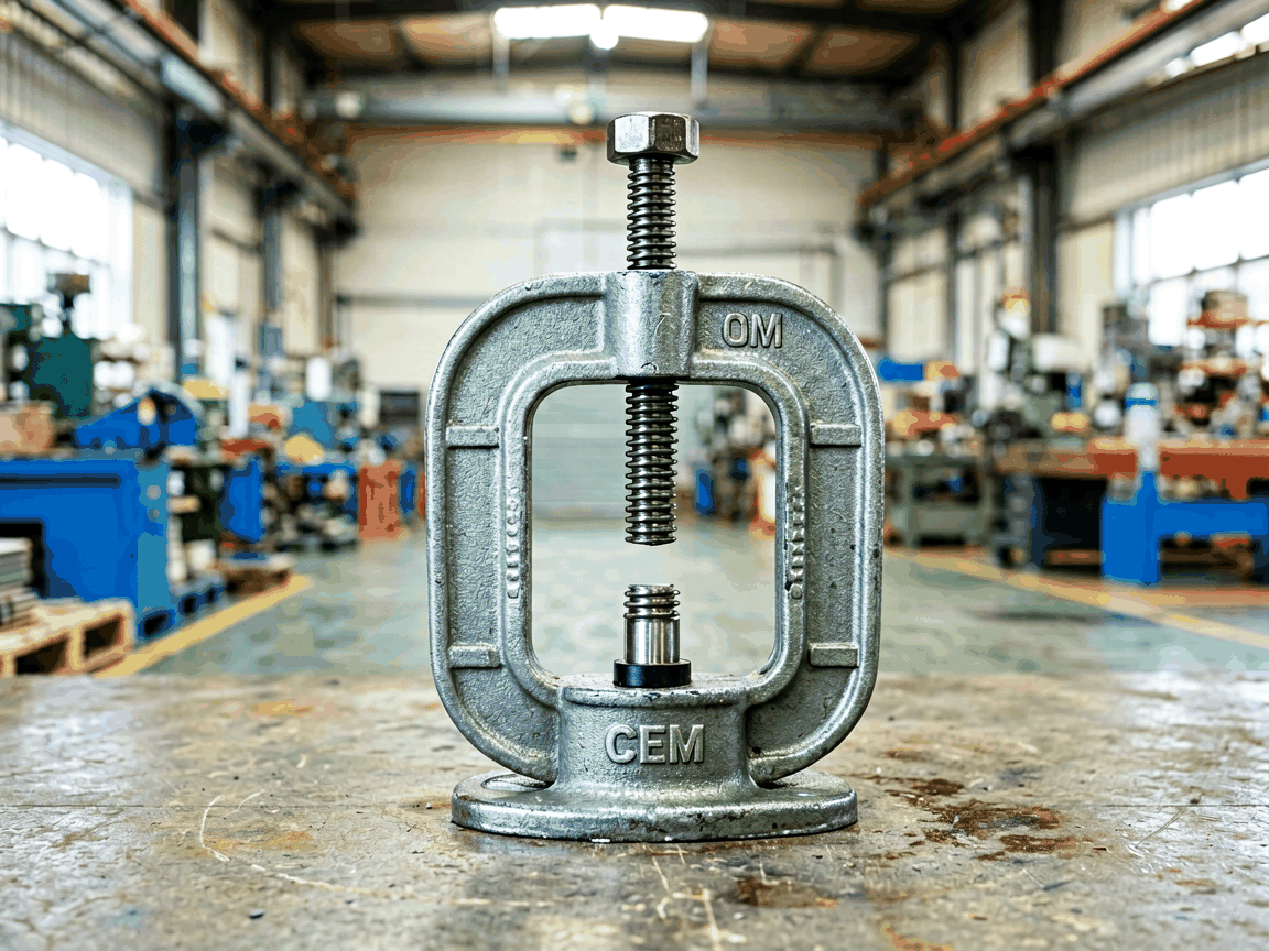
An OEM mason clamp factory specializes in producing custom-designed clamping systems for bricklaying, stone setting, and concrete formwork applications. These clamps are engineered to hold masonry units securely during mortar curing, ensuring alignment accuracy and preventing displacement under load. Unlike standard off-the-shelf models, OEM solutions are developed through direct collaboration with contractors, precast manufacturers, and equipment integrators to match specific wall thicknesses, bond patterns, and site logistics. The factory operates as an extension of the client’s engineering team, translating field requirements into manufacturable designs using DFM (Design for Manufacturability) principles. This approach reduces prototype cycles, minimizes field failures, and lowers total cost of ownership over the clamp’s service life.
Designing effective mason clamps begins with analyzing the forces exerted during construction: lateral pressure from wet concrete or grout, vertical load from stacked units, and torsional stress from wind or uneven settling. The clamp must resist these without deforming, slipping, or damaging the masonry surface. Key parameters include jaw opening range, clamping force capacity (typically 1.5–3x the expected service load), throat depth, and material yield strength. For example, a clamp intended for 200mm concrete blocks requires a minimum jaw adjustment of 250mm to accommodate tolerances and reinforcement. Engineers also evaluate contact pressure distribution to prevent spalling or cracking of soft bricks or aerated concrete. Finite element analysis (FEA) is commonly used during development to validate stress points before tooling.
Material choice directly impacts clamp durability, weight, and resistance to job site environments. Structural components are typically fabricated from cold-rolled steel (SPCC or equivalent) for frames and adjusting screws, while high-stress areas like jaws and pivot points use forged alloy steel (e.g., 4140 or 4340) hardened to HRC 40–45. For corrosion-prone environments—such as coastal projects or alkaline mortar exposure—hot-dip galvanizing (minimum 60µm zinc coating) or electrogalvanizing with chromate conversion coating is standard. Stainless steel (304 or 316 grade) is available for permanent installations or clean-room precast facilities where staining is unacceptable. Surface hardness and coating adhesion are verified via salt spray testing (ASTM B117) and Rockwell indentation tests during quality control.
OEM mason clamp factories offer customization across five primary dimensions: geometry, actuation method, load rating, accessory integration, and branding. Geometry adjustments include variable jaw profiles (flat, serrated, or contoured) to match specific masonry shapes, adjustable throat depths from 50mm to 300mm, and offset designs for corner or recess work. Actuation options range from manual toggle levers and ratchet mechanisms to hydraulic or pneumatic cylinders for automated precast lines. Load ratings are tailored to project specs—commonly 5kN to 50kN per clamp—based on safety factors per EN 1090 or ASTM F1122. Accessories such as magnetic base plates, quick-release pins, or dust boots are integrated per client request. Laser etching or stamping for OEM logos and part numbers is performed post-finish to ensure traceability.
Quality assurance in an OEM mason clamp factory follows a multi-stage process aligned with ISO 9001:2015 standards. Incoming raw materials are inspected via mill test certificates and verified for hardness, thickness, and coating weight. During production, critical dimensions (jaw alignment, screw thread pitch, hole tolerances) are checked using CMM (Coordinate Measuring Machine) or calibrated gauges at first article and periodic intervals. Each clamp undergoes functional testing: static load testing to 125% of rated capacity without permanent deformation, cycle testing (500 open/close operations) to assess wear on moving parts, and slip resistance testing under simulated mortar lubrication. Final inspection includes visual checks for burrs, sharp edges, and coating completeness. Test data is retained for traceability and provided to clients upon request as part of the PPAP (Production Part Approval Process) package.
OEM mason clamps are used where precision and repeatability are critical to structural integrity and aesthetic outcomes. In clay brick veneer installation, they maintain consistent joint width and prevent bowing during scaffolding removal. For architectural precast panels—such as those with exposed aggregate or custom finishes—clamps hold formwork inserts and lifting loops in place during casting, preventing floatation or shift. In refractory bricklaying for industrial furnaces, high-temperature-resistant clamps (made from heat-treated alloy steel) secure units during curing cycles exceeding 1000°C. They are also essential in glass block wall assembly, where even minor pressure misalignment can cause cracking. By eliminating reliance on manual bracing or ad-hoc clamping, these systems reduce labor variability and improve schedule predictability.
| Parameter | Typical Range | Customizable? |
|---|---|---|
| Jaw Opening Range | 100mm – 350mm | Yes |
| Clamping Force Capacity | 5kN – 50kN | Yes |
| Throat Depth | 50mm – 300mm | Yes |
| Frame Material | Cold-rolled steel, forged alloy | Yes |
| Surface Finish | Galvanized, painted, stainless | Yes |
| Actuation Method | Manual toggle, ratchet, hydraulic | Yes |
The OEM engagement typically begins with a technical consultation where the client provides site conditions, masonry specifications, load expectations, and integration constraints (e.g., compatibility with existing formwork or robotic handling systems). The factory’s engineering team responds with a concept sketch, load analysis, and material proposal within 3–5 business days. Upon approval, detailed 3D models and 2D drawings are generated for client review, including tolerance stacks and assembly sequences. Prototypes are produced using CNC machining or laser cutting for rapid iteration, followed by functional validation in a simulated environment. Once validated, tooling is finalized for production, and a first article inspection report is submitted. Lead time from design freeze to first production batch averages 6–8 weeks, depending on complexity and material availability.
For technical inquiries, custom design requests, or quotation assistance, contact our engineering team.
Request Technical Consultation




