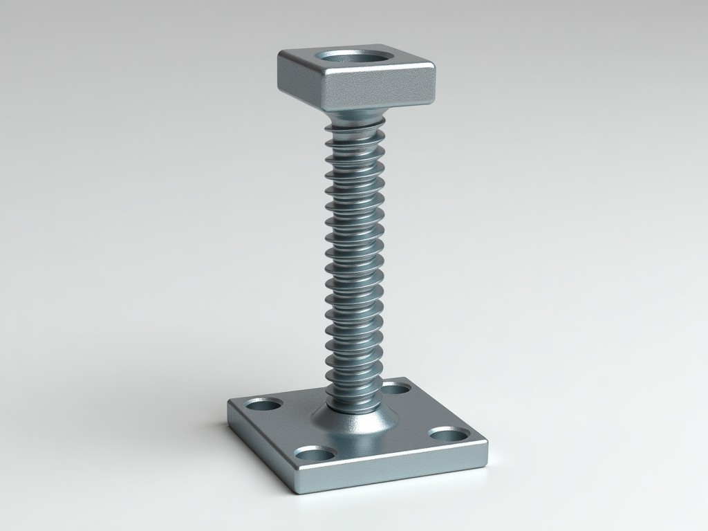
The galvanized screw jack base U head is a load-distributing component designed for mechanical lifting systems requiring vertical load transfer through a threaded mechanism. It integrates a U-shaped cradle with a hot-dip galvanized steel base plate to support vertical loads while accommodating rotational movement of the jack screw.
Unlike fixed-base supports, the U head allows controlled rotation and slight angular adjustment during operation, reducing binding stresses in the screw assembly under eccentric loading. The galvanization provides sacrificial corrosion protection, extending service life in outdoor or humid environments where uncoated steel would degrade within months.
The base plate is typically fabricated from structural grade steel (e.g., S235JR or equivalent) with a minimum thickness of 8 mm to resist deformation under sustained compressive loads. Hot-dip galvanizing follows EN ISO 1461 standards, achieving a zinc coating weight of approximately 550 g/m² (equivalent to ~75 µm thickness), which provides cathodic protection even if the coating is locally damaged.
The U head is forged or machined from the same base material to ensure metallurgical compatibility and consistent thermal expansion properties. Internal radii are designed to minimize stress concentration, with typical fillet radii of 3–5 mm depending on nominal load capacity. The opening width accommodates screw diameters from 20 mm to 50 mm, with clearances allowing for lubrication and thermal expansion.
Load ratings are determined by the base plate’s resistance to punching shear and bending, not the screw jack’s nominal capacity. For a standard 100 mm × 100 mm base plate with 8 mm thickness, the safe working load (SWL) under concentric compression is approximately 25 kN, assuming a safety factor of 3:1 relative to material yield strength. Eccentric loads reduce this capacity significantly; a 20 mm eccentricity can derate the SWL by up to 40%.
Engineers must verify that the jack’s maximum output force does not exceed the base’s derated capacity under expected load angles. Finite element analysis is recommended for custom geometries or dynamic loading scenarios. The U head’s contact surface with the screw should be lubricated with high-pressure grease (NLGI 2, EP additives) to prevent galling and ensure consistent torque transfer.
These components are commonly used in temporary support systems for formwork, façade retention, and structural shoring where adjustable height and corrosion resistance are required. In concrete formwork, the U head supports horizontal beams while allowing vertical adjustment to compensate for uneven substrates or deflection under wet concrete load. The galvanized base resists corrosion from alkaline concrete washout and rain exposure during multi-week pours.
In maritime or coastal infrastructure projects, the zinc coating prevents red rust formation that could compromise load transfer or seize the adjustment mechanism. Unlike painted alternatives, galvanization maintains protective properties even after abrasion from handling or rebar contact. The U head’s rotational freedom also accommodates minor misalignments in longitudinal formwork beams without inducing torsional stress in the screw.
Base plate dimensions can be adjusted to match specific load distributions or substrate constraints; common alternatives include 120 mm × 120 mm or 150 mm × 100 mm plates with thicknesses up to 12 mm for higher load applications. The U head geometry can be modified to accommodate square or rectangular screw profiles, though circular openings are standard for compatibility with threaded rods and machined screws.
Additional features such as pre-drilled anchoring holes, integrated leveling plates, or welded reinforcement gussets are available upon request. All custom variants undergo the same hot-dip galvanizing process to ensure complete coverage, including edges and weld zones. Post-galvanizing machining is avoided to prevent coating damage; instead, critical tolerances are achieved through precise pre-galvanizing forming or forging.
Dimensional verification includes base plate flatness (typically <0.5 mm deviation over 100 mm), U head opening width, and perpendicularity between the base plate and screw axis. Coating thickness is measured via magnetic induction at minimum five points per component, with adherence to EN ISO 1461 minimum local thickness of 55 µm. Visual inspection checks for uncoated spots, drips, or excessive roughness that could indicate inadequate pre-treatment.
Load testing is not performed on every unit due to the destructive nature of the test; instead, statistical process control monitors raw material yield strength and forming consistency. Mill certificates for base material and galvanizing batch reports are available upon request. Components are packaged with corrosion-inhibiting separators and stored in dry conditions prior to shipment to prevent wet storage staining.
| Parameter | Typical Value / Range | Notes |
|---|---|---|
| Base Plate Material | S235JR or equivalent | Minimum yield strength 235 MPa |
| Base Plate Thickness | 8 mm (standard), up to 12 mm | Selected based on load and span |
| Galvanizing Coating | 550 g/m² (~75 µm) | EN ISO 1461 compliant |
| Standard Base Size | 100 mm × 100 mm | Custom sizes available |
| Safe Working Load (Concentric) | ~25 kN | With 3:1 safety factor on yield |
| U Head Opening Diameter | 20 mm – 50 mm | Matches screw jack nominal size |
| Adjustment Range | Dependent on screw length | Typically 250 mm – 1000 mm stroke |
Proper selection requires matching the U head to the screw jack’s thread diameter and pitch, ensuring full thread engagement within the U head cavity. Mismatched components can lead to point loading, thread deformation, or sudden failure under load. Consultation with engineering teams is recommended for dynamic load applications, seismic zones, or installations involving lateral forces.
For technical inquiries, customization requests, or quotation support, please contact our engineering team. Provide application details including load magnitude, load orientation, environmental conditions, and required adjustment range to ensure accurate component specification.
Submit Inquiry




