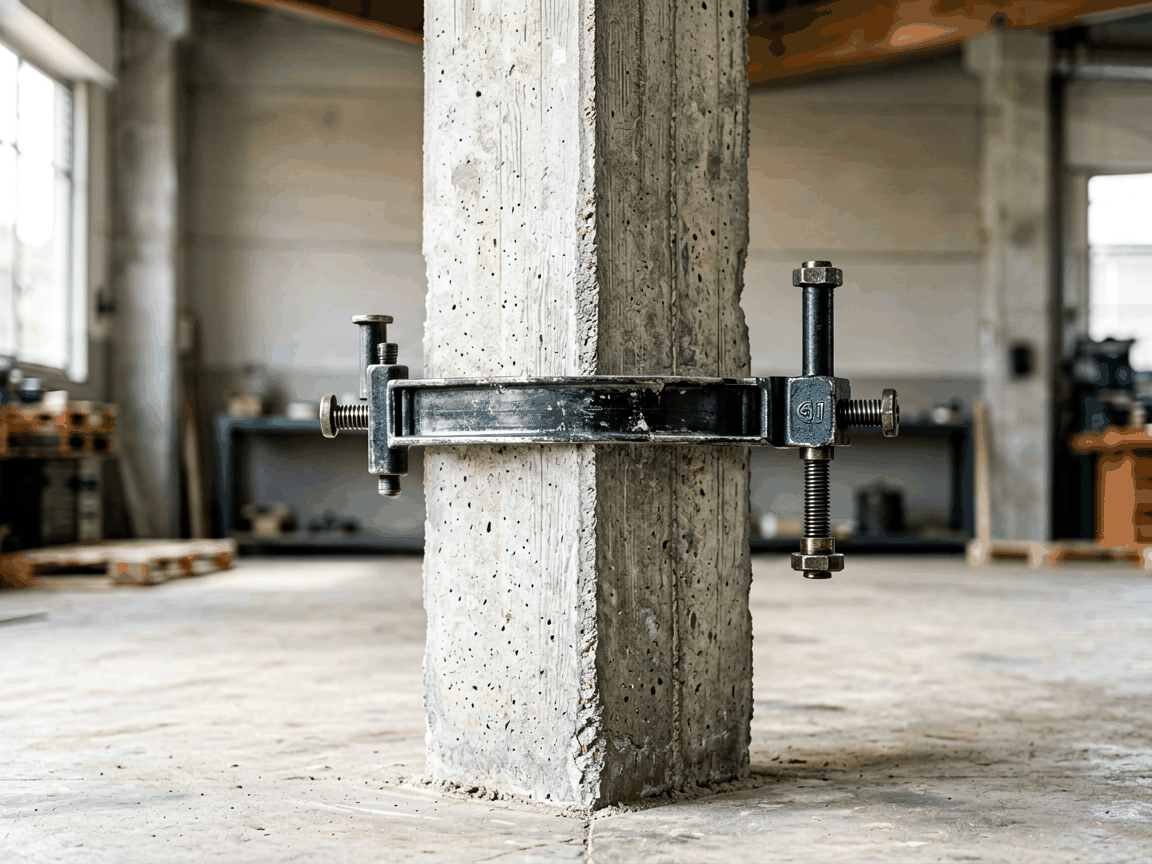
Concrete column form clamps are temporary fastening devices engineered to secure formwork panels around vertical concrete elements during pouring and curing. They transfer lateral pressure from fresh concrete to the form system, preventing bulging, misalignment, or blowouts that compromise structural integrity and surface finish. Unlike permanent anchors, these clamps are designed for rapid installation, adjustment, and removal without damaging the formwork or leaving residues that affect reuse cycles.
The primary function of a column clamp is to maintain precise dimensional control of the form cavity under hydrostatic load. Fresh concrete exerts lateral pressure that increases with pour height and rate, typically reaching 50–80 kN/m² at the base of a 3-meter column. Clamps must resist this force while allowing fine-tuning of panel gaps to accommodate concrete slump, aggregate size, and vibration effects. Their design directly influences the ability to achieve tolerances of ±5 mm or better on exposed architectural concrete.
Material selection balances strength, weight, and durability. Most industrial clamps use hot-dip galvanized steel for corrosion resistance in wet alkaline environments, with tensile strengths ranging from 400–550 MPa. High-cycle applications may specify stainless steel grades (e.g., 304 or 316) for prolonged exposure to chlorides or deicing agents. Aluminum alloys are occasionally used for lightweight handling in low-pressure scenarios, though their lower modulus requires larger cross-sections to match steel stiffness.
Clamping force capacity is the critical performance metric, defined as the maximum load the device can sustain before slip or deformation. Typical values range from 15 kN to 50 kN per clamp, depending on bolt size, lever arm length, and friction interface. This capacity must exceed the calculated formwork pressure with a safety factor of 1.5–2.0, accounting for dynamic effects during vibration and uneven pour rates.
Adjustment range determines adaptability to varying column dimensions. Most clamps offer 50–150 mm of travel via threaded spindles or sliding jaws, enabling use across standard column sizes (200 mm–800 mm square or diameter) without changing hardware. Fine-pitch threads (e.g., TR16x2) allow precise gap control under load, while coarse threads speed up initial positioning. Some designs incorporate swivel pads to accommodate non-parallel form faces caused by site tolerances.
Cycle life and wear resistance impact long-term cost. Repeated loading causes micro-deformation in threaded components and bearing surfaces. Hardened steel pins (58–62 HRC) and bronze bushings reduce galling in high-frequency use. Clamps intended for rental fleets often feature replaceable wear strips and corrosion indicators (e.g., zinc-rich paint that turns white when depleted) to simplify inspection and maintenance planning.
In high-rise construction, column clamps enable jump-form systems where forms are lifted in stages. Their quick-release mechanism allows crews to disengage and reset clamps at each lift without accessing the column interior, reducing cycle time by 30–50% compared to bolted alternatives. The ability to maintain alignment across multiple lifts is crucial for maintaining verticality tolerances in slip-formed cores.
Architectural concrete projects demand clamps that minimize surface marking. Non-marring pads made of UHMW-PE or nylon prevent imprinting on smooth form liners, while distributed load designs avoid localized dimpling. For exposed aggregate finishes, clamps must maintain consistent panel pressure to prevent paste bleed-through or stone displacement, directly affecting the final aesthetic quality.
Infrastructure works such as bridge piers and utility tunnels often involve large-diameter or irregularly shaped columns. Adjustable clamps with multi-point articulation conform to tapered or octagonal sections where rigid systems would gap or bind. In underwater applications, corrosion-resistant materials and sealed threads prevent seizure, enabling reliable operation after prolonged submersion.
| Type | Clamping Force (kN) | Adjustment Range (mm) | Typical Use Case |
|---|---|---|---|
| Wedge Action | 20–35 | 50–100 | Standard rectangular columns, general purpose |
| Threaded Spindle | 30–50 | 75–150 | High-pressure pours, tall columns, precision alignment |
| Lever Clamp | 15–25 | 30–80 | Low-height columns, rapid installation, rental fleets |
| Hydraulic | 40–60+ | Customizable | Large-diameter columns, heavy civil, prefabrication yards |
Wedge action clamps rely on mechanical interference to generate force, offering simplicity but limited adjustment once engaged. Threaded spindle types provide incremental control through rotation, allowing re-tightening as concrete settles or formwork creeps. Lever clamps prioritize speed with over-center locking, trading off maximum force for rapid deployment in repetitive tasks. Hydraulic systems deliver the highest and most uniform force, ideal for large sections where manual torque would be impractical or inconsistent.
Selection depends on pour rate, column geometry, reuse expectations, and labor considerations. For example, a 600 mm square column poured at 2 m/h with 25 mm slump concrete generates approximately 18 kN/m of lateral force at the base. A threaded spindle clamp rated for 40 kN with a 100 mm adjustment range would provide adequate capacity and flexibility for this scenario, allowing compensation for form bowing or aggregate segregation during the pour.
Begin by positioning form panels to the desired column dimensions, maintaining a uniform gap for concrete cover. Place the clamp over the panel joint, ensuring the force-applying face contacts the panel flatly without twisting. For threaded types, insert the spindle through the clamp body and engage the nut on the far panel. Tighten by hand until snug, then apply torque using a wrench to the specified value—typically 80–120 Nm for M16 spindles—monitoring panel alignment throughout.
After initial tightening, check for panel movement by attempting to slide the forms laterally; any slip indicates insufficient preload. Re-torque as needed, but avoid exceeding the clamp’s proof load to prevent permanent deformation. During pouring, monitor for signs of creep or relaxation, particularly in the first 30 minutes when concrete pressure rises rapidly. A final check before vibration ensures no loosening has occurred.
Release follows the reverse sequence: loosen the nut or lever, swing the clamp clear, and store in a dry location to prevent thread corrosion. Inspect for bent spindles, cracked bodies, or worn threads before reuse. Lubricate threads with anti-seize compound suitable for alkaline environments to maintain consistent torque characteristics across cycles. Document any damage or deformation for maintenance tracking.
Regular inspection extends service life and ensures safety. Check for cracks in high-stress areas using dye penetrant or magnetic particle testing, particularly around spindle holes and pivot points. Measure thread wear with gauges or calipers; replace if pitch diameter deviation exceeds 0.15 mm. Verify that moving parts articulate smoothly without binding or excessive play—more than 0.5 mm axial movement in the spindle indicates bushing wear.
Assess corrosion protection by examining coating integrity. Galvanized surfaces should show no red rust; white zinc oxide is acceptable but indicates consumption. For stainless steel, look for pitting or crevice corrosion in chloride-exposed environments. Replace any clamp with deformed load-bearing components, as residual strength cannot be reliably quantified after yielding.
Lubricate threaded interfaces and pivot points before each use with a moisture-displacing, high-pressure lubricant. Avoid greases that contain graphite or molybdenum disulfide in alkaline concrete environments, as they may accelerate corrosion. Store clamps in racks off the ground to prevent pooling water and mechanical damage. Maintain a log of usage cycles, inspections, and repairs to support predictive maintenance and rental fleet management.
Clamp dimensions can be tailored to non-standard column geometries, such as elliptical or tapered sections. Jaw width and throat depth are adjusted to match panel thickness and protrusion requirements. For columns exceeding 1000 mm in diameter, segmented clamp designs distribute force across multiple points to avoid localized overstress.
Thread specifications (e.g., TR20x2.5, UNC 3/4-10) can be modified to match existing equipment or improve adjustment speed. Spindle length is customized based on required travel and column size. Handle configurations—ratchet, T-bar, or hydraulic actuator interface—are selected according to torque availability and operator ergonomics.
Surface treatments include hot-dip galvanizing (minimum 60 µm), powder coating for color coding, or specialized coatings for chemical resistance. Non-marring pads can be specified in various thicknesses and materials (UHMW-PE, PTFE, nylon) to suit different form liners. Identification features such as laser-etched part numbers or color-coded handles aid in inventory control and correct deployment on site.
For rental or fleet applications, modular designs allow quick replacement of worn components (spindles, pads, pins) without discarding the entire clamp. Some manufacturers offer corrosion tracking systems where coating thickness is measured periodically to predict remaining life. These features reduce downtime and total cost of ownership in high-cycle environments.





