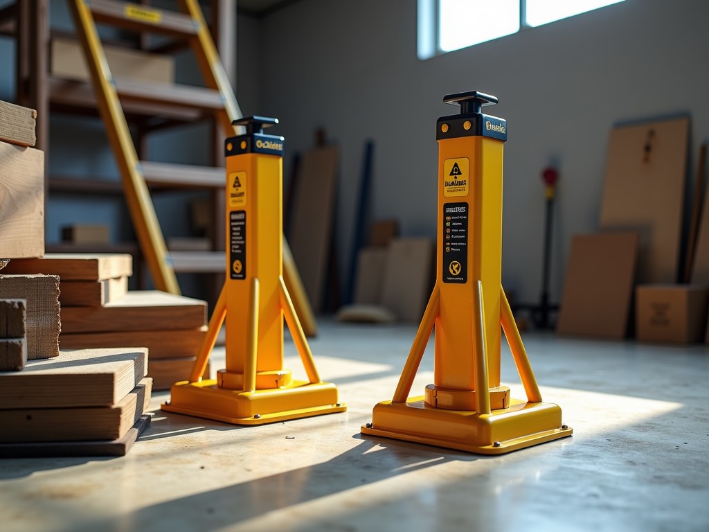
Baker scaffold leveling jacks are mechanical devices designed to compensate for uneven ground surfaces when erecting tubular steel scaffolding systems. They attach to the base of scaffold standards (uprights) and allow vertical adjustment through a threaded screw mechanism, enabling precise height correction to maintain scaffold plumb and level across varying terrain. This adjustment capability is essential for ensuring structural stability, load distribution integrity, and worker safety on construction sites where foundations are rarely perfectly flat.
The primary function of a leveling jack is to provide controlled vertical displacement at the scaffold base while maintaining axial load transfer from the standard to the foundation. Each jack consists of a threaded spindle, a base plate for load distribution, and a locking mechanism to prevent unintended rotation under load. When the scaffold encounters a slope or depression, the jack is wound down or up to bring the connected standard into vertical alignment, ensuring that horizontal ledgers and transoms remain level—a critical requirement for safe platform assembly and guardrail compliance.
Load capacity is determined by the spindle diameter, thread pitch, and material yield strength, with typical working loads ranging from 2,500 to 5,000 lbs per jack depending on model and configuration. The adjustment range commonly spans 12 to 24 inches, allowing compensation for significant grade variations without requiring extensive excavation or shoring. Proper installation requires the base plate to sit fully on a competent surface, with the spindle engaged sufficiently to resist buckling under eccentric loads.
Spindles are typically manufactured from cold-drawn carbon steel (such as 1018 or 1045) with tensile strengths between 60,000 and 80,000 psi, providing adequate strength-to-weight ratio for repeated adjustment cycles. Base plates are formed from hot-rolled steel plate, usually 1/4 inch thick, with dimensions designed to distribute loads over a minimum bearing area of 16 square inches to prevent soil punching or slab cracking. Thread forms are typically ACME or trapezoidal, chosen for their self-locking characteristics and resistance to vibration-induced loosening.
Surface treatments include hot-dip galvanizing per ASTM A123 or electro-galvanizing for corrosion resistance in outdoor environments, with zinc coating weights averaging 1.8 to 2.5 oz/ft². Alternative finishes such as powder coating are available upon request for specific architectural or environmental requirements. All load-bearing components undergo dimensional inspection post-manufacturing to verify thread engagement, base plate flatness, and spindle straightness within tolerances of ±0.005 inches per foot.
The threaded spindle operates via a forged steel handle or ratchet mechanism that converts rotary motion into linear displacement. Standard thread pitches range from 4 to 6 threads per inch, requiring approximately 16 to 24 revolutions per inch of adjustment—providing fine control while resisting accidental movement under load. Many models incorporate a captive handle design to prevent detachment during use, and some feature a swivel base plate to accommodate non-perpendicular loading angles without inducing side stress on the spindle.
To prevent over-extension, mechanical stops or visual indicators (such as painted bands on the spindle) are integrated to show maximum safe extension limits. Under no circumstances should the jack be extended beyond the manufacturer’s marked limit, as this reduces thread engagement and increases the risk of spindle bending or base plate tilting. Regular lubrication of the thread interface with lithium-based grease is recommended to maintain smooth operation and prevent galling, particularly in high-cycle applications.
Baker scaffold leveling jacks are specifically engineered for use with frame-and-brace scaffolding systems where modular frames are stacked vertically and braced diagonally. Unlike systems using adjustable base plates on pipe scaffolds, Baker frames rely on fixed-dimension vertical members, making base-level adjustment critical for achieving plumbness. The jacks interface directly with the lower lugs or sockets of the frame standards, transferring load through the spindle to the base plate and ultimately to the ground or slab.
They are indispensable in renovation projects, interior construction, and retrofit work where existing floor slopes, uneven slab penetrations, or varying substrate materials (such as soil, gravel, or compacted fill) prevent direct frame placement. In high-rise construction, they enable the initial lift of scaffolding towers on uneven foundations before subsequent tiers are stacked, ensuring that each level builds upon a vertically aligned base. Their use reduces the need for custom shimming or time-consuming ground preparation, directly impacting labor efficiency and project timelines.
The effectiveness of a leveling jack depends not only on its load capacity but also on how well the base plate distributes that load across the supporting surface. On soft or granular soils, the 1/4-inch thick base plate may require supplementary support such as timber mats or steel spreaders to reduce bearing pressure below the soil’s allowable capacity—typically 1,000 to 3,000 psf for compacted fill. On concrete slabs, point loading must be checked to ensure localized stress does not exceed the slab’s compressive strength or cause spalling at joints.
Eccentric loading—where the scaffold load does not act through the spindle’s central axis—can induce bending moments in the jack assembly. To minimize this, the scaffold standard must be seated squarely in the jack’s top receptor, and the base plate should be positioned as close as possible to vertically aligned with the applied load. In cases where significant lateral forces are expected (such as from wind or material hoists), additional bracing or anchoring to the structure may be required, as leveling jacks are designed primarily for vertical load support, not lateral resistance.
Routine inspection should focus on thread integrity, base plate flatness, spindle straightness, and coating condition. Threads must be free of galling, deformation, or debris that could impede smooth rotation. The spindle should exhibit no visible bending when rotated under no load—any wobble indicates potential straightness loss from overloading or impact. Base plates must sit flat on a reference surface; gaps exceeding 1/16 inch under a straightedge suggest warping from excessive heat or mechanical damage.
Galvanized coatings should be inspected for white rust (zinc hydroxide) or red rust (iron oxide), particularly in crevices or damaged areas. Minor coating loss can be touched up with zinc-rich paint, but significant substrate exposure warrants re-galvanizing or replacement. With proper maintenance, leveling jacks typically endure 5 to 10 years of regular construction use, though service life varies significantly based on environmental exposure, frequency of adjustment, and adherence to load limits.
| Parameter | Standard Model | Heavy-Duty Model |
|---|---|---|
| Spindle Diameter | 1.0 inch | 1.25 inch |
| Thread Type | ACME 4 TPI | ACME 4 TPI |
| Working Load Limit | 2,500 lbs | 5,000 lbs |
| Adjustment Range | 12 inches | 24 inches |
| Base Plate Thickness | 1/4 inch | 3/8 inch |
| Base Plate Dimensions | 4" x 4" | 6" x 6" |
| Finish | Hot-Dip Galvanized | Hot-Dip Galvanized |
| Typical Applications | Light to medium frame scaffolding, interior work | High-load shoring, exterior façades, heavy equipment support |
Note: Values represent typical configurations. Actual specifications may vary based on manufacturer design updates or project-specific requirements. Custom spindle lengths, base plate geometries, or thread types are available upon request for specialized applications such as confined spaces or corrosive environments.
While standard configurations cover the majority of scaffolding applications, certain projects require tailored solutions. Available customizations include extended spindle lengths beyond 24 inches for deep foundations or basement-level work, reduced-diameter spindles for use in tight spaces between existing structures, and stainless steel construction (typically 304 or 316 grade) for environments with high chloride exposure or stringent hygiene requirements.
Base plate modifications such as oval or rectangular shapes can be provided to match irregular footprints or interface with proprietary scaffolding connectors. Thread locking features—such as nylon inserts or mechanical detents—may be added to prevent vibrational loosening in high-traffic or seismic zones. All custom requests are evaluated for structural integrity, with load ratings recalculated based on modified dimensions and material properties.
Manufacturing quality control begins with material certification, verifying steel grade and mechanical properties via mill test reports. Dimensional checks are performed at key stages: spindle diameter and straightness after drawing, thread form accuracy post-rolling, and base plate flatness before welding or stamping. Load testing is conducted on sample units using hydraulic presses to verify ultimate strength and deformation characteristics, with acceptance criteria typically set at 1.5 times the working load limit without permanent deformation.
Coating thickness is measured using magnetic induction or ultrasonic methods to ensure compliance with ASTM A123 standards. Visual and tactile inspections assess surface finish uniformity and adhesion. Final assembly includes functional testing of the adjustment mechanism—confirming smooth rotation, proper handle engagement, and effective locking under simulated load. Traceability is maintained through lot numbers stamped on non-critical surfaces, enabling material and process tracking throughout the product lifecycle.
*All technical specifications are subject to change without notice. Consult manufacturer documentation for project-specific guidance.





